37
ENGLISH
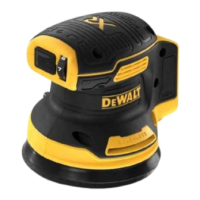
Slider Switch (Fig.D)
CAUTION: Hold the main handle and body of the tool
firmly to maintain control of the tool at start up and
during use and until the wheel or accessory stops rotating.
Make sure the wheel has come to a complete stop be fore
laying the tooldown.
NOTE: To reduce unexpected tool movement, do not switch
the tool on or off while under load conditions. Allow the sander
to run up to full speed before touching the work surface. Lift the
tool from the surface before turning the tool off. Allow the tool
to stop rotating before putting itdown.
WARNING: Before connecting the tool to a power supply,
be sure the slider switch is in the off position by pressing
the rear part of the switch and releasing. Ensure the
slider switch is in the off position as described above after
any interruption in power supply to the tool, such as a
deadbattery.
To start the tool, slide the ON/OFF slider switch
3
toward
the front of the tool. To stop the tool, release the ON/OFF
sliderswitch.
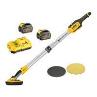
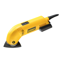
Attaching Sanding Discs (Fig.C)
Your DCE800 drywall sander is designed to use 225mm
sanding discs
11
. Sanding discs for the DCE800 attach with
hook andloop.
The recommended sanding discs are available at extra cost from
your local dealer or authorised DeWALT servicecentre.
To Attach Sanding Disc to the Sanding Pad
(Fig.C)
1. Turn the sander over so that the sanding pad
9
is
facingupward.
2. Clean the dust from the sanding padface.
3. Hold the pad with one hand to keep it fromrotating.
4. With the other hand, center and place the sanding disc
11
directly on top of thepad. If using paper sanding discs,
ensure any ventilation holes in sanding disc align with
ventilation holes in sandingpad.
Inserting and Removing the Battery Pack
from the Tool (Fig.B)
NOTE: Make sure your battery pack
1
is fullycharged.
To Install the Battery Pack into the Tool Handle
1. Align the battery pack with the rails inside the tool’s
handle(Fig. B).
2. Slide it into the handle until the battery pack is firmly seated
in the tool and ensure that you hear the lock snap intoplace.
ASSEMBLY AND ADJUSTMENTS
WARNING: To reduce the risk of serious personal
injury, turn tool off and disconnect battery pack
before making any adjustments or removing/
installing attachments or accessories. An accidental
start-up can causeinjury.
WARNING: Use only DeWALT batteries andchargers.
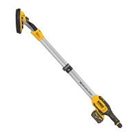
Description (Fig. A)
WARNING: Never modify the power tool or any part of it.
Damage or personal injury couldresult.
1
Battery
2
Battery release button
3
ON/OFF slider switch
4
Speed control dial
5
Main handle
6
Main tube
7
Dust extraction port
8
Tube expansion lever
9
Sanding pad
Intended Use
This drywall sander is designed for professional
sandingapplications.
Do not use under wet conditions or in the presence of
flammable liquids orgases.
This drywall sander is a professional powertool.
Do not let children come into contact with the tool. Supervision
is required when inexperienced operators use thistool.
• Young children and the infirm. This appliance is not
intended for use by young children or infirm persons
withoutsupervision.
• This product is not intended for use by persons (including
children) suffering from diminished physical, sensory or
mental abilities; lack of experience, knowledge or skills
unless they are supervised by a person responsible for their
safety. Children should never be left alone with thisproduct.
Date Code Position (Fig.B)
The production date code
10
consists of a 4-digit year followed
by a 2-digit week and is extended by a 2-digit factorycode.
g
Wear earprotection.
f
Wear eyeprotection.
To Remove the Battery Pack from the Tool
1. Press the battery release button
2
and firmly pull the
battery pack out of the toolhandle.
2. Insert battery pack into thecharger.
Fuel Gauge Battery Packs (Fig.B)
Some DeWALT battery packs include a fuel gauge, which
consists of three green LED lights that indicate the level of
charge remaining in the batterypack.
To actuate the fuel gauge, press and hold the fuel gauge
button
16
. A combination of the three green LED lights will
illuminate, designating the level of charge left. When the level
of charge in the battery is below the usable limit, the fuel gauge
will not illuminate and the battery will need to berecharged.
NOTE: The fuel gauge is only an indication of the charge left on
the battery pack. It does not indicate tool functionality and is
subject to variation based on product components, temperature
and end-userapplication.
 Loading...