38
ENGLISH
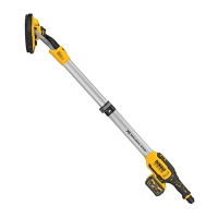
Sanding Drywall (Fig.I)
WARNING: To reduce the risk of personal injury, ALWAYS
wear a respirator approved for “Dust andMist” and
connect the drywall sander to a suitable dustextractor.
The drywall sander has an articulating sanding head. The head
can swivel in multiple directions, allowing the abrasive pad to
conform to the work surface. This action enables you to sand
the top, middle, and bottom of a wall or ceiling joint without
changingposition.
1. Turn the vacuum cleaner switch ON (I).
2. Turn drywall sander switchON.
3. Position the drywall sander lightly against the work surface.
Apply just enough pressure to align the sanding head with
the worksurface.
Proper hand position requires one hand on the main handle
5
and one hand on the main tube
6
.
Proper Hand Position (Fig.G)
WARNING: To reduce the risk of serious personal injury,
ALWAYS use proper hand position asshown.
WARNING: To reduce the risk of serious personal
injury, ALWAYS hold securely in anticipation of a
suddenreaction.
OPERATION
Instructions for Use
WARNING: Always observe the safety instructions and
applicableregulations.
WARNING: To reduce the risk of serious personal
injury, turn tool off and disconnect battery pack
before making any adjustments or removing/
installing attachments or accessories. An accidental
start-up can causeinjury.
DeWALT Tool Tag Ready (Fig. H)
Optional Accessory
Your sander comes with mounting holes
15
and fasteners
for installing a DeWALT Tool Tag. You will need a T15 bit tip to
install the tag. The DeWALT Tool Tag is designed for tracking and
locating professional power tools, equipment, and machines
using the DeWALT Tool Connect™ app. For proper installation of
the DeWALT Tool Tag refer to the DeWALT Tool Tagmanual.
Wireless Tool Control (Fig.A)
CAUTION: Read all saftey warnings, instruction and
specifications of the appliance which is paired with
thetool.
Your tool is equipped with a Wireless Tool Control transmitter
which allows your tool to be wirelessly paired with another
Wireless Tool Control device, such as a dustextractor.
To pair your tool using Wireless Tool Control, press and
hold the trigger switch
2
on the tool and the Wireless Tool
Control pairing button on the seperate device. An LED on the
seperate device will let you know when your tool has been
successfullypaired.
Attaching an AirLock™ Compatible Dust
Extractor (Fig.F)
Your drywall sander is compatible with the DeWALT AirLock™
connection system. The AirLock™ allows for a fast, secure
connection between the AirLock™ connector
13
and sander's
dust extraction port
7
.
1. Ensure the collar on the AirLock™ connector is in the unlock
position. (Refer to Fig.F.) Align notches
14
on collar and
AirLock™ connector as shown for unlock and lockpositions.
2. Push the AirLock™ connector onto the adapter
connectorpoint.
3. Rotate the collar to the lockedposition.
NOTE: The ball bearings inside collar lock into slot and
secure the connection. The power tool is now securely
connected to the dustextractor.
NOTE: The sleeve of the dust extraction port can be
removed if damaged and replaced by the user. The sleeve is
available as an optional accessory and can be replaced using
ascrewdriver.
Expanding the Main Tube (Fig. E)
The main tube of the DCE800 can be expanded to various
desiredlengths.
• To expand the main tube, release the tube expansion
lever
8
and extend the tube to the desiredlength.
• Close the tube expansion lever to lock the main tube
inplace.
Brush-Type Skirt (Fig.C)
A brush-type skirt
12
surrounds the abrasive pad on the
DCE800. This skirt serves two purposes:
• It extends below the surface of the abrasive pad to prevent
the abrasive from “gouging” thework.
• It helps contain the drywall dust until the vacuum cleaner
pulls itaway.
If the skirt is damaged or if it is worn excessively it should be
replaced by a DeWALT authorised servicecentre.
Speed Control Dial (Fig.A)
The DCE800 sander is equipped with a variable speed control.
Adjust the speed by turning the speed control dial
4
. The speed
control dial is numbered “1” through “5”. The setting “1” is the
slowest speed (approximately 1200RPM) and “5” is the fastest
speed (approximately 2400RPM).
Use the higher speed settings for fast stock removal. Use
the lower speed settings to reduce removal rate for more
precisecontrol.
No-Volt
The No-volt function stops the sander from restarting without
the switch being cycled if there is a break in the powersupply.
For continuous operation, slide the switch toward the front of
the tool and press the forward part of the switch inward. To stop
the tool while operating in continuous mode, press the rear part
of the slider switch andrelease.
 Loading...