ENGLISH
8
Variable Speed Trigger and Forward/
Reverse Control Button (Fig. A)
The tool is turned on and off by pulling and releasing the
variable speed trigger
1
. The farther the trigger is depressed,
the higher the speed of the tool. Your tool is equipped with
a brake. The chuck will stop as soon as the trigger switch is
fullyreleased.
A forward/reverse control button
4
determines the
rotational direction of the tool and also serves as a
lock-offbutton.
• To select forward rotation (clockwise), release the trigger
and depress the forward/reverse control button on the
right side of thetool.
• To select reverse (counterclockwise), depress the
forward/reverse control button on the left side of
thetool.
NOTE: The center position of the control button locks the
tool in the off position. When changing the position of the
control button, be sure the trigger isreleased.
NOTE: Continuous use in variable speed range is not
recommended. It may damage the switch and should
beavoided.
NOTE: The first time the tool is run after changing the
direction of rotation, you may hear a click on start up. This is
normal and does not indicate aproblem.
Proper Hand Position (Fig.E)
WARNING: To reduce the risk of serious personal injury,
ALWAYS use proper hand position as shown.
WARNING: To reduce the risk of serious personal
injury, ALWAYS hold securely in anticipation of a
suddenreaction.
Proper hand position requires one hand on the main
handle
11
.
Installing and Removing the Battery Pack
(Fig.F)
NOTE: For best results, make sure your battery pack is
fullycharged.
To install the battery pack
1
into the tool handle, align the
battery pack with the rails inside the tool’s handle and slide it
into the handle until the battery pack is firmly seated in the
tool and ensure that it does notdisengage.
To remove the battery pack from the tool, press the release
button
2
and firmly pull the battery pack out of the tool
handle. Insert it into the charger as described in the charger
section of thismanual.
OPERATION
WARNING: To reduce the risk of serious personal
injury, turn unit off and remove the battery pack
before making any adjustments or removing/
installing attachments or accessories. An
accidental start‑up can causeinjury.
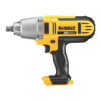
Speed Selector (Fig.A)
Your tool is equipped with a speed selector
7
which allows
you to select one of three speeds. Select the speed based on
the application and control the speed of the tool using the
variable speed trigger switch
3
.
Speed 1 0–400 rpm
Speed 2 0–1200 rpm
Speed 3 0–1900 rpm
Anvil (Fig.A, F)
WARNING: Use only impact accessories. Non‑impact
accessories may break and cause a hazardous
condition. Inspect accessories prior to use to ensure that
it con tains nocracks.
CAUTION: Inspect anvils, detent pins and hog rings
prior to use. Missing or damaged items should be
replaced beforeuse.
Place the switch in the locked off (center) position or remove
battery pack before changingaccessories.
Anvil with Detent Pin DCF899
To install an accessory on the anvil, align the hole in
the side of the accessory with the detent pin
9
on the
anvil
5
. Press the accessory on until the detent pin engages
in the hole. Depression of detent pin may be necessary to aid
installation ofaccessory.
To remove an accessory, depress the detent pin through
the hole and pull the accessoryoff.
Anvil with Hog Ring DCF899H, DCF897
To install an accessory on the hog ring anvil, firmly push
accessory onto the anvil
5
. The hog ring
8
compresses
to allow the accessory to slide on. After accessory is
installed, the hog ring applies pressure to help provide
accessoryretention.
To remove an accessory, grasp the accessory and firmly
pull itoff.
NOTE: The thru-hole allows an O-ring with retaining pin or a
1-piece retaining pin to be used to help secure sockets and
accessories to the tool.
Anvil with Quick Release Chuck DCF898
NOTE: The chuck accepts 1/4" (6.35 mm) hex accessories
and 1" (25.4 mm) bit tipsonly.
To install an accessory, fully insert the accessory. The
accessory is locked into place (Fig.F).
To remove an accessory, pull the chuck collar
10
away
from the front of the tool. Remove the accessory (Fig.F).
ASSEMBLY AND ADJUSTMENTS
WARNING: To reduce the risk of serious personal
injury, turn unit off and remove the battery pack
before making any adjustments or removing/
installing attachments or accessories. An
accidental start‑up can causeinjury.
SAVE THESE INSTRUCTIONS FOR
FUTURE USE
Worklight (Fig.A)
The worklight
6
is activated when the trigger switch is
depressed, and will automatically turn off 20 seconds after