ENGLISH
12
The RBRC® Seal
The RBRC® (Rechargeable Battery
Recycling Corporation) Seal on the nickel
cadmium, nickel metal hydride or lithium-ion
batteries (or battery packs) indicates that the
costs to recycle these batteries (or battery
packs) at the end of their useful life have already been paid
by
. In some areas, it is illegal to place spent nickel
cadmium, nickel metal hydride or lithium-ion batteries in the
trash or municipal solid waste stream and the Call 2 Recycle®
program provides an environmentally conscious alternative.
Call 2 Recycle, Inc., in cooperation with
and other
battery users, has established the program in the United
States and Canada to facilitate the collection of spent nickel
cadmium, nickel metal hydride or lithium-ion batteries. Help
protect our environment and conserve natural resources by
returning the spent nickel cadmium, nickel metal hydride or
lithium-ion batteries to an authorized
service center
or to your local retailer for recycling. You may also contact
your local recycling center for information on where to drop off
the spent battery. RBRC® is a registered trademark of Call 2
Recycle, Inc.
Operation
Operating Tips
• To extend battery life per charge, turn the laser off when it
is not in use.
• To ensure the accuracy of your work, check the laser
calibration often. Refer to Calibrating the Laser.
• Before attempting to use the laser, make sure the tool is
positioned on a relatively smooth, secure surface.
• Always mark the center of the laser line or dot. If you
mark different parts of the beam at different times you will
introduce error into your measurements.
• To increase working distance and accuracy, set up the
laser in the middle of your working area.
• When attaching to a tripod or wall, mount the laser
securely.
• When working indoors, a slow rotary head speed will
produce a visibly brighter line, a faster rotary head speed
will produce a visibly solid line.
• To increase beam visibility, wear Laser Enhancement
Glass es and/or use a Laser Target Card to help find the
beam.
• Extreme temperature changes can cause movement or
shifting of building structures, metal tripods, equipment,
etc., which can effect accuracy. Check your accuracy often
while working.
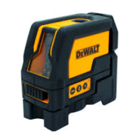
• When working with the
Digital Laser Detector, set
the laser’s rotation speed to the fastest setting.
• If the laser is dropped or has suffers a sharp blow, have
the calibration system checked by a qualified service
center before using the laser.
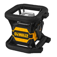
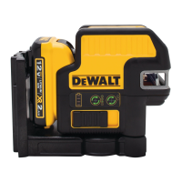
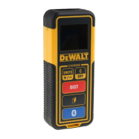
Control Panel (Fig.
A
)
The laser is primarily controlled by the power button
1
, the
mode button
2
, the speed button
3
and the scan mode button
4
. These features are then modified when used with either the
Axis selection button
5
(DW080LRS/LGS in Slope mode only),
or the two direction/elevation adjustment buttons
6
and
7
.
The direction/elevation adjustment buttons control the rotational
direction of the laser head as well as adjust the elevation of the
beam when the unit is in slope mode. These buttons can also
be used to incrementally rotate the beam when the unit is in
Scan mode.
The buttons on the DW080LRS/DW080LGS control panel and
the DW080LRS/DW080LGS Remote keypad work the same,
unless otherwise indicated.
Power Button
The Power button is used to turn the laser unit on and off.
• To power ON the DW080LRS/LGS laser unit, press the
Power button once.
• To completely power OFF the DW080
LRS/LGS laser
unit, press the power button for 3 sec.
Speed/Rotation Button
The speed button
3
is used to adjust the rotation speed of the
laser beam through its 4 preset speeds (150, 300, 600, and
1200 RPM).
Scan Mode Button
The scan mode button
4
is used to make the laser head
sweep back and forth, creating a short, bright laser line. This
short line is much brighter and more visible than when the unit
is in full rotation mode.
Using Scan Mode
• To enter Scan Mode, push and release the scan mode
button
4
. To cycle through the scan angles, continue to
press the button until you reach the desired angle.
• The direction of the scan zone can be controlled with the
arrow buttons
6
and
7
.
Slope Mode Button
• To activate Slope Mode press the slope mode button
2
.
• To return to self-leveling mode and re-engage full self-
leveling, press and hold the mode button
2
again.
Setting the Slope Direction
When Slope Mode is activated, the unit automatically engages
the X- Axis. This allows you to slope the laser in the direction of
the X-Axis, as indicated by the “gunsights” on the rollcage.
The LED light
11
or
12
indicates the current slope direction.
In certain situations, it may be desirable to slope the laser in
the Y-axis. The direction of Slope Mode can be changed back
and forth between the Y-axis and the X-axis by pressing the
X-Y axis button
5
. The selected axis is identified by LED light
24
or
25
.