6
FIELD CALIBRATION CHECK
CHECKING ACCURACY – PLUMB (FIG. 5–6)
Checking the plumb calibration of the laser can be most accurately done when there is a substantial amount of vertical height available, ideally
25’ (7.5 m), with one person on the floor positioning the laser and another person near a ceiling to mark the dot created by the beam on
the ceiling (Fig. 5). It is important to conduct a calibration check using a distance no shorter than the distance of the applications for which
the tool will be used.
1. Start by marking a point on the floor.
2. Place the laser on the floor so that the down dot beam is centered on the point marked on the floor.
3. Allow time for the laser to settle to plumb and mark the center of the dot created by the up beam.
4. Turn the laser 180° as shown (Fig. 6), making sure that the down dot beam is still centered on the point previously marked on the floor.
5. Allow time for the laser to settle to plumb and mark the center of the dot created by the up beam.
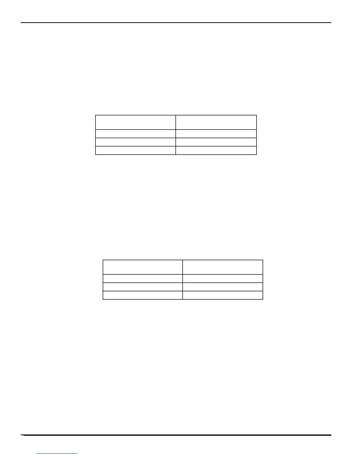
If the measurement between the two marks is greater than shown below, the laser is no longer in calibration.
Distance Between Floor and Ceiling Measurement Between Marks
15' (4.5 m) 1/8" (3 mm)
30' (9 m) 1/4” (6 mm)
50' (15 m) 11/32" (9 mm)
CHECKING ACCURACY - LEVEL (FIG. 7–10)
Checking the level calibration of the laser unit requires two parallel walls at least 20’ (6 m) apart. It is important to conduct a calibration check using a distance no
shorter than the distance of the applications for which the tool will be used.
1. Place unit 2”–3” (5–8 cm) from first wall, facing the wall (Fig. 7).
2. Mark the beam position on the first wall.
3. Turn the unit 180˚, and mark the beam position on the second wall (Fig. 8).
4. Place the unit 2”–3” (5-8 cm) from the second wall, facing the wall (Fig. 9).
5. Adjust the height of the unit until the beam hits the mark from step 3.
6. Turn the unit 180˚, and aim the beam near the mark on the first wall from step 2 (Fig. 10).
7. Measure the vertical distance between the beam and the mark.
8. If the measurement is greater than the values shown below, the laser must be serviced at an authorized service center.
Repeat steps 1 through 8 to check the front beam, left beam, and right beam.
Distance Between Walls Measurement Between Marks
15' (4.5 m) 1/8" (3 mm)
30' (9 m) 1/4” (6 mm)
50' (15 m) 11/32" (9 mm)
TROUBLESHOOTING
THE LASER DOES NOT TURN ON
• Makesurebatteriesareinstalledaccordingto(+),(-)markingsonbatterydoor.
• Makesurethebatteriesareinproperworkingcondition.Ifindoubt,tryinstallingnewbatteries.
• Makesurethatthebatterycontactsarecleanandfreeofrustorcorrosion.Besuretokeepthelaserleveldryanduseonlynew,high-qualitybatteriestoreduce
the chance of battery leakage.
• Ifthelaserhasbeenstoredinextremelyhottemperatures,allowittocool.
THE LASER BEAMS FLASH (FIG. 4)
The DW08301 laser level has been designed to self-level up to 4° in all directions when positioned as shown in Figure 4. If the laser is tilted so much that internal
mechanism cannot plumb itself, the laser will flash —the tilt range has been exceeded. THE FLASHING BEAMS CREATED BY THE LASER ARE NOT LEVEL OR PLUMB
AND SHOULD NOT BE USED FOR DETERMINING OR MARKING LEVEL OR PLUMB. Try repositioning the laser on a more level surface.
THE LASER BEAMS WILL NOT STOP MOVING
The DW08301 is a precision instrument. Therefore, if it is not positioned on a stable (and motionless) surface, the tool will continue to try to find plumb. If the beam will
not stop moving, try placing the tool on a more stable surface. Also, try to make sure that the surface is relatively flat, so that the laser is stable.
*Accuracy spec assumes laser is positioned on a surface within 4° of level.
 Loading...