19
ENGLISH
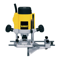
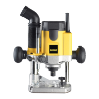
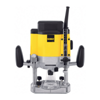
Intended Use
Your
high performance router DW615 has been
designed for professional heavy duty routing applications.
DO NOT use under wet conditions or in the presence of
flammable liquids orgases.
This router is a professional power tool.
DO NOT let children come into contact with the tool.
Supervision is required when inexperienced operators use
thistool.
• Young children and the infirm. This appliance is not
intended for use by young children or infirm persons
without supervision.
• This product is not intended for use by persons (including
children) suffering from diminished physical, sensory or
mental abilities; lack of experience, knowledge or skills
unless they are supervised by a person responsible for their
safety. Children should never be left alone with thisproduct.
ASSEMBLY AND ADJUSTMENTS
WARNING: To reduce the risk of serious personal
injury, turn tool off and disconnect tool from power
source before making any adjustments or removing/
installing attachments or accessories. An accidental
start-up can cause injury.
Cutters
The tooling can be used with the complete range of commercial
cutters (e.g: straight, rebate, profile cutter, slotter cutter or
grooved knife) with the following technical data:
1. Shank diameter 6 mm—8 mm
2. Cutter speed of min. 30000/min
WARNING: DW615 max diameter to use:
Straight, rabbet or profile cutter with a max shank
diameter of 8 mm, a max diameter of 36 mm and a max
cutting depth of 10 mm;
• Slotter cutter with a max shank diameter of 8 mm and
a max diameter 25 mm;
• Grooved knife with a max shank diameter of 8 mm, a
max diameter of 40 mm and a cutting width of 4 mm.
Inserting and Removing a Cutter (Fig. B)
1. Press and hold down the spindle lock
7
.
2. Using the 17 mm wrench, loosen the collet nut
8
a few
turns and insert a cutter.
3. Tighten the collet nut and release the spindle lock.
WARNING: Never tighten the collet nut without a cutter
in the collet.
Replacing the Collet Assembly (Fig. C)
Your router is supplied with a 8 mm (GB: 1/4") collet fitted to
the tool. Two other precision collets are also available to suit the
cutter used. The collet and the collet nut are inseparable.
1. Loosen the collet nut
8
completely.
2. Remove the collet assembly
13
.
3. Fit a new assembly and tighten the collet nut
8
.
Setting the Electronic Speed Control Dial
(Fig. A)
The speed is infinitely variable from 8000 to 24000 min
-1
using
the electronic speed control dial
12
.
1. Turn the electronic speed control dial to the required level.
2. Generally, use the low setting for large diameter cutters
and the high setting for small diameter cutters. The correct
setting, however, is a matter of experience.
1 ~ 8200 min
-1
2 ~ 12000 min
-1
3 ~ 16200 min
-1
4 ~ 20500 min
-1
5 ~ 24000 min
-1
Adjusting the Depth of Cut (Fig. D)
Depth Adjustment Using the Graduation and
Revolver Depth Stop
1. Loosen the depth stop locking bolt
5
.
2. Unlock the plunge limiter
4
by turning it counterclockwise.
3. Lower the router carriage until the cutter is in contact with
the workpiece.
4. Tighten the plunge limiter
4
.
5. Set the exact depth of cut using the graduation
2
or place a
depth template between the depth stop
3
and the revolver
depth stop
6
. The adjustment range is indicated by the
arrows
14
.
6. Tighten the depth stop locking bolt
5
.
Triple Depth Adjustment
The revolver depth stop
6
can be used to set three different
depths. This is particularly useful for deep cuts, performed
insteps.
1. Place a depth template between the depth stop
3
and the
revolver depth stop
6
to adjust the exact cutting depth.
2. If required, set all three screws.
Depth Adjustment with Router Installed in
Inverted Position
1. Set the depth of cut prior to installing the router in
invertedposition.
WARNING: For installing the router in inverted
position, refer to the relevant instruction manual on the
stationarytool.
A fine depth adjuster (DE6956) is available as an accessory.
Fitting the Parallel Fence (Fig. A, E)
1. Fit the guide rods
15
to the router base
11
.
2. Tighten the locking bolts
10
.
3. Slide the parallel fence
16
over the rods.
4. Tighten the locking bolts
17
temporarily.
Adjusting the Parallel Fence (Fig. E)
1. Draw a cutting line on the material.
2. Lower the router carriage until the cutter is in contact with
the workpiece.
 Loading...