Do you have a question about the DeWalt DW682 and is the answer not in the manual?
Guidelines for maintaining a safe work environment and electrical precautions.
Advice on operator alertness, PPE, and preventing accidental starts.
Covers proper hand position, switching, and fundamental biscuit joint techniques.
Guidance on positioning biscuits and performing test cuts for accuracy.
Methods for creating biscuit joints in edge, frame, and corner configurations.
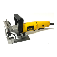
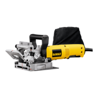
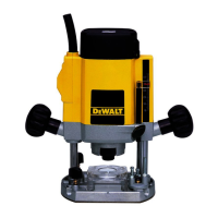
The DEWALT DW682 Biscuit Jointer is a professional power tool designed for making flat dowel joints in wood and wood products. It is engineered for precision and durability, making it a reliable partner for professional power tool users.
The biscuit jointer operates by cutting crescent-shaped slots into the edges of workpieces. These slots are then fitted with compressed wooden biscuits, which, when glued, expand and create strong, accurate joints. The tool features an On/Off switch for operation and a lock-on button for continuous use, enhancing user comfort during extended tasks.
The plunge depth of the cutter can be adjusted to match various biscuit sizes (#0, #10, #20), with a maximum cutting depth of approximately 22 mm. This adjustment is made using a dedicated knob, ensuring that the slots are cut to the correct depth for optimal joint strength. For fine-tuning, a hex screwdriver can be used to adjust the plunge depth, allowing for compensation for possible tolerances in biscuit slot sizes.
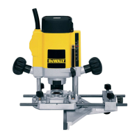
An adjustable fence is a key feature, enabling precise setting of the slot cutting point. The fence height can be adjusted by slackening a locking knob and setting the height adjuster. The scale under the locking knob indicates the distance between the cutter's center and the fence surface. The fence angle can also be tilted to the required position by slackening and tightening a star knob, facilitating angled joints.
For situations where the fence cannot be used, such as making T-joints, the jointer base includes markings for proper tool alignment. These markings help center the tool on workpieces of different thicknesses and indicate the length of the cut, preventing breakthrough.
The tool is equipped with anti-slipping pins that help stabilize it during cutting, reducing the tendency to slide. These pins can be retracted when working on visible parts of the workpiece to avoid scratching.
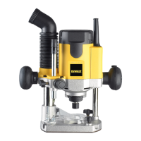
Dust extraction is an integral part of the design, with an outlet that can be connected to either a dustbag or a dust extractor. This feature helps maintain a clean work area and reduces exposure to dust particles, which can cause breathing difficulties.
Operating the biscuit jointer involves several steps to ensure safe and accurate joints. Before starting, users must select the appropriate biscuit size and adjust the plunge depth accordingly. It is always recommended to make a trial cut on scrap wood to verify the settings.
For edge joints, biscuits are typically spaced at 15-25 cm intervals, with outer biscuits positioned 5-7.5 cm from the workpiece ends. When joining narrow workpieces, the exposed tip of the biscuit may need to be trimmed after gluing. For thicker workpieces, pairs of biscuits can be used for added strength. Mating pieces should be marked with a set square to ensure proper alignment.
Cutting biscuit slots involves aligning the tool's center marking with the workpiece's marking line, switching the tool on, and allowing the cutter to reach full speed. The fence is then firmly pushed against the workpiece, and the cutter is plunged until the stop is reached. After the cut, the tool is allowed to retract, and then switched off.
Assembling workpieces involves checking the fit of the joints, applying a suitable glue to the biscuit slots and mating surfaces, inserting the biscuits, and clamping the workpieces until the glue dries.
The DW682 supports various joint types:
The DEWALT DW682 is designed for long-term operation with minimal maintenance, but proper care and regular cleaning are essential for satisfactory performance.
Key maintenance tasks include:
The tool requires no additional lubrication. It is important to always turn off the tool and disconnect it from the power source before performing any adjustments, changing accessories, or repairs to prevent accidental start-ups and potential injury.
| Input power | 600 W |
|---|---|
| Output power | 335 W |
| Power source | AC |
| Idle speed | 10000 RPM |
| Vibration level | 2.5 m/s² |
| Sound power level | 100 dB |
| Planing depth (max) | 20 mm |
| Planning width (max) | 100 mm |
| Sound pressure level | 82 dB |
| Sound level uncertainty | 3 dB |
| Vibration level uncertainty | 1.5 m/s² |
| Chip thickness (max) | - mm |
| Dust bag included | Yes |
| Product color | Black, Yellow |
| Depth | 320 mm |
|---|---|
| Height | 150 mm |
| Weight | 3000 g |