FIG. 5
H
L
M
N
FIG. 6
1. To replace bit, depress both spindle lock (C) and collet lock (B) and turn collet grip counter-
clockwise.
2. Insert bit.
WARNING: The bits are sharp and should be handled with great care.
CAUTION: When replacing bits, do not insert cutting flutes into the collet. This may result in
broken bits.
3. While depressing both spindle and collet locks, turn the collet grip clockwise to firmly tighten
the collet. For some heavy duty applications, it may be necessary to use a wrench to further
tighten the nut (D) while depressing the spindle lock (C).
4. Attach guide.
CAUTION: Never tighten the collet without a bit installed.
This tool comes with both 1/8" and 1/4" collets. To change collets, remove the collet nut and
insert the desired collet.
Depth Guide (Fig. 3)
To attach depth guide to the motor unit,
TURN OFF TOOL AND DISCONNECT FROM POWER
SUPPLY.
Depth guide snaps onto locators as shown. Keep depth guide in place at all times during oper-
ation of the tool. For best results, adjust the guide using knob (E) to allow the bit to protrude
about 1/8" past the material to be cut.
Side Handle DW6619 (Fig. 4)
When operating the tool, use the side handle for optimum control. To attach the side handle to
the motor unit,
TURN OFF TOOL AND DISCONNECT FROM POWER SUPPLY.
1. Remove depth guide.
2. Loosen knob (F) until the collar of the tool is able to fit into the strap (G) of the side handle.
3. Align the locator on the tool with the locator on the side handle. (Detail) Tighten knob (F).
4. Snap the depth guide over the side handle strap (G) from the opposite side. Keep the depth
guide in place at all times during operation of the tool.
5. For best results, adjust the guide using knob (E) to allow the bit to protrude about 1/8"
through the material to be cut.
6. To remove the side handle, remove the depth guide, loosen the knob (F) until the tool can
come off the locator and slip out of the strap (G).
7. Reattach the depth guide.
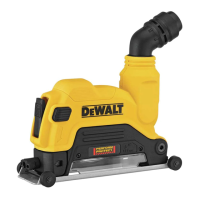
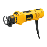
Circle Cutter DW6621 (Fig. 5)
To attach the circle cutter to the motor unit,
TURN OFF THE TOOL AND DISCONNECT FROM
POWER SUPPLY.
1. Remove the depth guide.
2. Loosen knob (H) until the collar of the tool is able to fit into the strap (J) of the circle cutter.
3. Align the locator on the tool with the locator on the circle cutter. (Detail) Tighten knob (H).
4. Disassemble the depth guide collar. Snap the upper half (M) onto the strap (J).
5. Loosen knob (L) and extend circle cutter frame to the limit of travel.
6. Insert knob (E) through the frame (N).
7. Set depth of cut for your material and tighten knobs (E) and (L).
8. Measure to the center of the circle you wish to cut and adjust the length of the guide to that
radius.
9. Tighten the knob (O) holding the centerpoint in position.
10. Drill a 5/32" hole in the material to be cut at the center of the radius.
11. Plug in the tool, start the motor and allow the tool to spin up to speed.
12. Position the center point into the hole and plunge the cutter into the material.
13. With firm pressure, hold the center point in place and move the cutter counterclockwise
around to the finish.
CAUTION: At the finish of the circle, the material may drop out. Hold the tool with both hands
to maintain control.
14.To remove the circle cutter, loosen knob (H) until the tool can come off the locator and slip
out of the strap (J).
15.Reassemble the depth guide and reattach.
Operation
CUTTING A HOLE FOR AN ELECTRICAL OUTLET (FIG. 6)
WARNING: Shut off all live electric circuits to any areas where cut outs will be made.
1. Push any wiring deeply into the outlet box to avoid damage from the cutting bit.
2. Before hanging the sheet covering the outlet, mark the approximate location of the center of
the outlet on the wall board. Check the cutting bit depth against the side of the board to be
sure it will cut entirely through the material.
3. Tack the sheet in place with a few fasteners avoiding the stud holding the outlet. This allows
the wall board to flex slightly around the protruding fixture box.
4. Turn the cut-out tool on. Holding the tool firmly with both hands, (Fig. 6) plunge the bit
straight into the center of the outlet.
5. Cut to the right until the edge of the box is touched. Pull out just enough for the bit to clear
the edge of the box. Plunge in again holding the bit gently against the outside of the box.
6. Follow the outside of the box as shown keeping slight pressure against the box. This will
minimize wandering and give you a clean precise cut.
7. Remove the waste and dust from the outlet. Finish fastening the sheet of wall board.
Maintenance
The tool should be cleaned with a blast of air at least once a week, to eject as much dust as
possible. This will increase the life of the brushes and bearings inside the motor. Always use
appropriate safety equipment when using compressed air to clean a tool.
Although the tool’s plastic case is solvent resistant, you should never use solvents or harsh
chemicals to clean it. Wipe the non-metallic parts of the tool with a dry cloth.
Lubrication
All bearings are factory lubricated for the life of the tool.
Accessories
Recommended accessories for use with your tool are available at extra cost from your local
dealer or authorized service center. If you need assistance in locating any accessory for your
tool, contact: D
EWALT Industrial Tool Co., 701 East Joppa Road, Baltimore, MD 21286.
CAUTION: Do not use double ended bits. The use of any other accessory not recommended
for use with this tool could be hazardous.
Repairs
To assure product SAFETY and RELIABILITY, repairs, maintenance and adjustment (including
brush inspection and replacement) should be performed by authorized service centers or other
qualified service organizations, always using identical replacement parts.
Three Year Limited Warranty
DEWALT will repair, without charge, any defects due to faulty materials or workmanship for three
years from the date of purchase. This warranty does not cover part failure due to normal wear
or tool abuse. For further detail of warranty coverage and warranty repair information, visit
www.dewalt.com or call 1-800-4-D
EWALT (1-800-433-9258). This warranty does not apply to
accessories or damage caused where repairs have been made or attempted by others. This
warranty gives you specific legal rights and you may have other rights which vary in certain
states or provinces.
In addition to the warranty, D
EWALT tools are covered by our:
1 YEAR FREE SERVICE
D
EWALT will maintain the tool and replace worn parts caused by normal use, for free, any time
during the first year after purchase.
90 DAY MONEY BACK GUARANTEE
If you are not completely satisfied with the performance of your D
EWALT Power Tool, Laser, or
Nailer for any reason, you can return it within 90 days from the date of purchase with a receipt
for a full refund – no questions asked.
FREE WARNING LABEL REPLACEMENT: If your warning labels become illegible or are miss-
ing, call 1-800-4-D
EWALT for a free replacement.
FIG. 1 FIG. 2
D
C
B
A
“O”
“I”
COLLET GRIP
DOUILLE DE
SERRAGE
ABRAZADERA
DEL COLLAR
GUIDE
GUIDE
GUÍA
FIG. 3
FIG. 4
E
LOCATOR
POSITIONNEUR
LOCALIZADOR
POUR TOUTE QUESTION OU REMARQUE AU SUJET DE CET OUTIL OU DE TOUT
AUTRE OUTIL D
EWALT, COMPOSER LE NUMÉRO SANS FRAIS : 1 800 4-DEWALT
(1 800 433-9258)
Directives de sécurité d’ordre général
AVERTISSEMENT! S’assurer de lire et de bien comprendre toutes les
directives. Le non-respect des directives décrites ci-après pourrait être la
cause de chocs électriques, d’incendies et/ou de blessures graves.
CONSERVER CES DIRECTIVES
AIRE DE TRAVAIL
• L’aire de travail doit être propre et bien éclairée. Les établis encombrés et le manque de
lumière peuvent entraîner des accidents.
• Ne pas faire fonctionner des outils électriques dans des atmosphères explosives,
comme en présence de liquides, de gaz et de poussières inflammables. Les outils élec-
triques produisent des étincelles qui peuvent enflammer la poussière ou les vapeurs.
• Tenir les spectateurs, les enfants et les visiteurs à l’écart lorsqu’on utilise l’outil. Les
distractions peuvent entraîner une perte de maîtrise.
RÈGLES DE SÉCURITÉ RELATIVES À L’ÉLECTRICITÉ
• Les outils mis à la terre doivent être branchés dans une prise correctement installée
et mise à la terre tel que l’indiquent les codes et règlements en vigueur. Ne jamais retir-
er la broche de mise à la terre ou modifier la prise en aucune façon. Ne pas utiliser de
fiche d’adaptation. Consulter un électricien qualifié s’il y a un doute en ce qui con-
cerne la mise à la terre de la prise. En cas de mauvais fonctionnement ou de bris des out-
ils, la mise à la terre offre un chemin de faible résistance afin d’empêcher l’électrocution de
l’utilisateur. S’applique uniquement aux outils de classe I (mis à la terre).
• Les outils à double isolation sont pourvus d’une fiche polarisée (une lame est plus
large que l’autre). Cette fiche ne peut être branchée dans une prise polarisée que dans
un seul sens. Si la fiche ne peut être branchée dans la prise, inverser la fiche. Si on
n’arrive pas à la brancher, communiquer avec un électricien qualifié afin qu’il installe
une prise polarisée. Ne pas modifier la fiche. La double isolation élimine le besoin du
système de rallonge d’alimentation à trois fils et de bloc d’alimentation avec mise à la terre.
S’applique uniquement aux outils de classe II (à double isolation).
• Éviter tout contact corporel avec des surfaces mises à la terre, comme des tuyaux,
des radiateurs, des cuisinières et des réfrigérateurs. Le risque de choc électrique aug-
mente si le corps est mis à la terre.
• Ne pas exposer les outils électriques à la pluie ou à l’eau. L’infiltration d’eau dans un outil
électrique augmente le risque de choc électrique.
• Manipuler le cordon avec soin. Ne jamais s’en servir pour transporter l’outil ou pour
tirer la fiche hors de la prise. Tenir le cordon à l’écart de la chaleur, de l’huile, des arêtes
vives ou des pièces mobiles. Remplacer immédiatement les cordons endommagés, car ils
augmentent le risque de choc électrique.
• Lorsqu’on utilise un outil électrique à l’extérieur, il faut employer une rallongeportant
l’inscription “W-A” ou “W.” Ces rallonges sont conçues pour l’utilisation à l’extérieur et
réduisent le risque de choc électrique. S’il y a lieu d’utiliser une rallonge, s’assurer que celle-
ci est de calibre suffisamment élevé pour acheminer le courant nécessaire au fonctionnement
de l’outil. Une rallonge de calibre trop faible pourrait causer une chute de tension se traduisant
par une perte de courant et une surchauffe. Le tableau qui suit indique le calibre approprié
selon la longueur de la rallonge et l’intensité indiquée sur la plaque signalétique. En cas de
doute, utiliser le calibre supérieur suivant. Plus le numéro de calibre est petit, plus le calibre
de la rallonge est élevé.
Calibre minimal des cordons de rallonge
TensionLongueur totale du cordon en meters
120 V De 0 à 7 De 7 à 15 De 15 à 30 De 30 à 45
240 V De 0 à 7 De 7 à 15 De 15 à 39 De 30 à 45
Intensité (A)
Au Au Calibre moyen de fil
moins plus
0-6 18 16 16 14
SÉCURITÉ PERSONNELLE
• Demeurer alerte, prêter attention à ce que l’on fait et faire preuve de bons sens
lorsqu’on utilise un outil électrique. Ne pas utiliser un outil lorsqu’on ressent de lafa-
tigue ou après avoir consommé des drogues, de l’alcool, ou des médicaments. Un
moment d’inattention durant l’utilisation d’outils électriques peut entraîner de graves blessures.
• Porter des vêtements appropriés. Ne pas porter des vêtements amples ou des bijoux.
Les cheveux longs doivent être retenus. Tenir les cheveux, les vêtements et les gants
F
G
LOCATOR
POSITIONNEUR
LOCALIZADOR
LOCATOR
POSITIONNEUR
LOCALIZADOR
J
E
O
 Loading...