9
ENGLISH
OPERATION
Instructions for Use
WARNING: Always observe the safety instructions and
applicableregulations.
WARNING: To reduce the risk of serious personal
injury, turn tool off and disconnect tool from power
source before making any adjustments or removing/
installing attachments or accessories. An accidental
start-up can cause injury.
WARNING: Do not remove guards (
7
, Fig.B). Serious
injury couldresult.
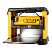
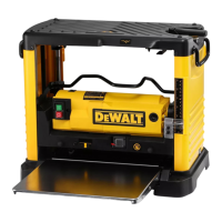
Transporting the Planer (Fig. A)
WARNING: For your own safety, it is recommended
that two people carry this machine or serious injury
couldresult.
When moving your planer, carry it either by the side carrying
handles
2
or by the handles
3
at the base of theplaner.
Bench Mounting (Fig. A)
To facilitate bench mounting, two different sized holes
4
are
provided on the four corners of your planer. If mounting the
planer with bolts, use the larger holes. If mounting the planer
with nails or screws, use the smaller holes. It is not necessary to
use both sets ofholes.
Always mount your planer firmly to prevent movement. To
enhance the tool’s portability, it can be mounted to a piece of
12.7mm or thicker plywood which can then be clamped to your
work support or moved to other job sites andreclamped.
NOTE: If you elect to mount your planer onto a piece of
plywood, make sure that the mounting screws don’t protrude
from the bottom of the wood. The plywood must sit flush on
the worksupport.
CAUTION: The mounting surface should not be warped or
otherwiseuneven.
To Attach the Depth Adjustment Crank
Handle (Fig. C)
1. Remove the screw located in the crank handleshaft.
2. Insert the crank handle
5
over theshaft.
3. Secure in place with the screw and T-wrench
8
provided.
Dust Ejection Ports (Fig. D)
Your planer comes with a dust ejection port. The round
port
9
as shown in Figure. F is for use with a 100mm dust
collectorhose.
To Set Up Dust Ejection (Fig.D)
WARNING: Do not operate your planer without the
dust ejection port locked into place. Do not insert
anything into the dust ejection chute unless the
planer is unplugged and you are clearing a clog or
obstruction in the unit. Do not get your face or eyes
near the dust ejection port when the planer is in
operation. Serious injury couldresult.
ASSEMBLY AND ADJUSTMENTS
WARNING: To reduce the risk of serious personal
injury, turn tool off and disconnect tool from power
source before making any adjustments or removing/
installing attachments or accessories. An accidental
start-up can causeinjury.
mental abilities; lack of experience, knowledge or skills
unless they are supervised by a person responsible for their
safety. Children should never be left alone with thisproduct.
WARNING: Chips are ejected at significant velocity. Keep
hands and face clear of dust ejectionport.
1. Select the port
9
.
2. Depress the lock button
11
on the chip ejection chute
10
.
3. Slide the notches in the dust port over the pins on the chip
ejectionchute.
4. Rotate the port until the button engages the dust ejection
chute and locks inplace.
To Remove the Dust Ejection Port (Fig.D)
1. Use the T-wrench to depress the lock button
11
on the
dustchute.
2. Twist the port until the pins are disengaged from the
notches on theport.
3. Pull the dust ejection port off of the dustchute.
Depth Adjustment (Fig. E)
Depth Adjustment Scale (Fig.E)
The depth adjustment scale
14
, located on the right front of
your planer, indicates the finished thickness of your workpiece.
One rotation of the depth adjustment crank is equal to 1.6mm,
half rotation is equal to 0.8mm,etc.
Depth Adjustment Crank
Turning the crank clockwise lowers the cutterhead. Turning the
crank counterclockwise raises thecutterhead.
Turret Stop (Fig. F)
Your planer is equipped with a turret stop
17
for planing
multiple boards to the same pre-set depth. Stops are set at
3mm, 6.5mm, 12.7mm, 319mm, 25.5mm, and 32mm.
To Set the Minimum Depth to Which the Carriage
can Travel with the Turret Stop
1. Be sure the carriage is set above 32mm before trying to set
the turretstop.
2. Turn the dial on the front left of the planer until the desired
thickness setting aligns with the red indicator, then lower
thecarriage.
3. Plane the workpiece at desired increments until the correct
final thickness isachieved.
NOTE: Do not use force to crank the carriage below the
level that the turret stop indicates. Permanent damage to
the height adjust ment system on your planer willresult.

 Loading...