ENGLISH
6
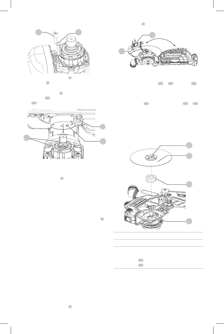
Fig. C
18 19
3. Press the front shroud button
7
and the side
shroud button
8
at the same time to fully open the
cuttingshroud.
4. Loosen the collar screw
2
on the cutting shroud and
align the tabs
20
on the cutting shroud with the
slots
21
on the grinder gearcase.
Fig. D
20
2
21
5. Rotate the shroud into the desired working position. The
shroud should be positioned between the spindle and
the operator to provide optimumefficiency.
6. Tighten the collar screw
2
to secure the cutting shroud
on the gear case. Do not operate the grinder with a
loose cuttingshroud.
7. To remove the cutting shroud, loosen the collar screw,
rotate the cutting shroud to align the slots and tabs and
pull up on the cuttingshroud.
NOTE: The cutting shroud is pre-adjusted to the diameter of
the gear case hub at the factory. If, after a period of time, the
cutting shroud becomes loose, tighten the collar screw
2
.
Only adjust the collar screw when it is on the grinder
otherwise the collar can bedamaged.
NOTICE: If cutting shroud cannot be secured by
tightening the collar screw, do not use tool. Take the
tool and cutting shroud to a service center to repair or
replace the cuttingshroud.
Mounting and Using Type 1 (Cutting)
Diamond Wheels (Fig.A, E, F)
WARNING: Only Type 1 Diamond Wheels shall be
used with cutting shroud. Do not cut metal. Do not
use with bonded abrasivewheels.
CAUTION: Do not use the shroud with the grinder
flanges. Only use the shroud with the flanges provided
withit.
1. With the cutting shroud attached to the grinder,
press the front shroud button
7
and the side
shroud button
8
at the same time to fully open the
cuttingshroud.
Fig. E
8
7
2. Remove the backing flange that is on the grinder (and
keep it for conversion back to agrinder).
3. Install the backing flange,
12
or
14
, on spindle
25
.
IMPORTANT: The DWE46125 comes with two sets of
flanges. Refer to the Flange/Grinder Compatibility
Chart at the end of this section for properuse.
4. Place the wheel
24
on the locking flange
11
or
13
,
and place both on the spindle, against the backing
flange, centering the wheel on the raised center of the
backingflange.
5. While depressing the spindle lock button, tighten the
locking flange using awrench.
6. To remove the wheel, depress the spindle lock button
and loosen the lockingflange.
Fig. F
11
12
24
25
Flange / Grinder Compatibility Chart
Flange set Grinder
Short (silver)
flange set:
Locking flange
11
Backing flange
12
DCG413