ENGLISH
5
Minimum Gauge for Cord Sets
Volts
Total Length of Cord in Feet
(meters)
120 V 25 (7.6) 50 (15.2) 100 (30.5) 150 (45.7)
240 V 50 (15.2) 100 (30.5) 200 (61.0) 300 (91.4)
Ampere Rating
American Wire Gauge
More
Than
Not
More
Than
0 6 18 16 16 14
6 10 18 16 14 12
10 12 16 16 14 12
12 16 14 12 Not Recommended
WARNING: If the plug or power cord is damaged,
it must be replaced by the manufacturer or its
representative or by an equally qualified person to
avoiddanger.
The label on your tool may include the following symbols. The
symbols and their definitions are asfollows:
V ......................... volts
Hz .......................hertz
min ..................... minutes
or DC ......direct current
...................... Class I Construction
(grounded)
…/min ..............per minute
BPM .................... beats per minute
IPM ..................... impacts per minute
RPM .................... revolutions per
minute
sfpm ................... surface feet per
minute
SPM .................... strokes per minute
A ......................... amperes
W ........................watts
or AC ...........alternating current
or AC/DC .... alternating or
direct current
...................... Class II
Construction
(double insulated)
n
o
.......................no load speed
n .........................rated speed
......................earthing terminal
.....................safety alert symbol
.....................visible radiation
..................... wear respiratory
protection
..................... wear eye
protection
..................... wear hearing
protection
..................... read all
documentation
SAVE THESE INSTRUCTIONS FOR
FUTURE USE
Intended Use
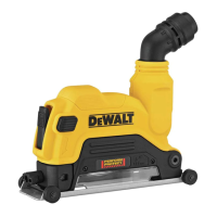
Your cutting shroud has been designed for professional
concrete and masonry or stone cutting, or tuckpoint
applications with a Diamond coated wheel that is designed
for the application. It is not intended for use with metal
or wood. Using the appropriate grinder, wheel and dust
extractor vacuum it can be used to remove the vast majority
of static and airborne dust which without the use of the
cutting shroud could otherwise contaminate the working
environment or pose an increased health risk to the
operator and those in closeproximity.
DO NOT use under wet conditions or in presence of
flammable liquids orgases.
The cutting shroud is a professional tool.
DO NOT let children come into contact with the tool.
Supervision is required when inexperienced operators use
thistool.
Cutting Shroud / Grinder Compatible List
DWE46125
Keyless gear case: DWE43214, DWE43214N,
DWE43214NVS, DWE43240INOX, DWE43231VS,
DWE43244N, DWE43240VS, DWE46253, DWE46202,
DWE43265N, DWE43840CN
DWE43113, DWE43115, DWE43115N, DWE43066,
DWE43066N, DWE43116, DWE43116N, DWE43114,
DWE43114N, DWE43131, DWE43144, DWE43144N,
DWE43140, DWE46103, DWE46153, DWE46155
DWE402G, DWE402K, DWE402, DWE402N
DWE4222, DWE4222N, DWE4214
DCG414
DWE4020, DWE4120, DWE4011
DCG413
DWE46127
DWE4517, DWE4519, DWE4557, DWE4559N, DWE4559CN,
D28499X, DWE4597, DWE4597N, DWE4599N
NOTE: The DWE46125 must be only used with 4.5"
(115mm) or 5" (125mm) accessories. The DWE46127 must
be only used with 7" (180mm)accessories.
ASSEMBLY AND ADJUSTMENTS
WARNING: To reduce the risk of serious personal
injury, turn unit off and disconnect it from
power source before making any adjustments or
removing/installing attachments or accessories.
An accidental start-up can causeinjury.
Mounting and Removing Cutting Shroud
(Fig. B–D)
1. Follow the mounting and removing guard instructions
in the tool manual to remove the guard fromgrinder.
Retain the original parts from your grinder to properly
reassemble the grinderguard.
2. To mount cutting shroud on the gear case, remove the
guard release lever
15
, guard release lever screw
17
and screw
16
shown in Figure B. Insert the supplied
screws: stop screw
18
and screw
19
as shown in
Figure C to protect the threadholes.
Then mount cuttingshroud. Refer to the Cutting
Shroud / Grinder Compatible List for the list of
compatible grinders with a keyless gearcase.
Fig. B
16 17
15

 Loading...