ENGLISH
6
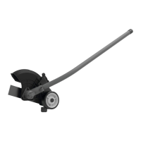
Blade (Fig.C)
WARNING: To reduce the risk of serious personal
injury, turn unit off and remove the battery pack
before making any adjustments or removing/
installing attachments or accessories, or prior to
cleaning. An accidental start‑up can causeinjury.
WARNING: Wait for blade to come to completestop.
The blade
1
, spacer
11
and a hex head nut
12
should be
attached to your edger in the order shown. Please check
that the blade has been properly mounted before using your
edger. The edger blade has two wear indicators that show
when blade needs to bereplaced.
NOTE: To increase blade life, keep initial cutting depth at
minimum and increase depth setting as bladewears.
Blade Replacement
WARNING: Use gloves and proper eye protection. Turn
the edger on its side. Be careful of sharp edges of blade.
WARNING: Blade rotates momentarily after the switch
isreleased.
1. Removebattery.
2. Remove edger attachment from thepowerhead. Reverse
the steps under Assembling the Edger Attachment to
thePowerhead.
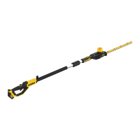
Assembling the Edger Attachment to the
Powerhead (Fig.A,B, E)
1. The upper powerhead pole
5
is equipped with three
latching holes
6
,
7
,
8
for the latching button
9
.
2. When installing the edger attachment pole
3
into the
upper powerhead pole
5
, use the arrows
10
to align
the latching button
9
with latching hole
6
, as shown
in Fig. B
NOTE: To properly engage the latching button
9
with
the latching hole
6
, slightly rotate the powerhead
pole
5
and move it axially until the latching button
engages the latching hole.
DO NOT insert the latching button into latching hole
7
,
or
8
. Doing so will position the edger head in an
incorrect orientation which could create a safety hazard.
Latching holes
7
and
8
are for otherattachments.
3. Turn the knob
4
to secure theattachment.
4. When properly assembled, it should look like Fig. E. If it
does not, do not use, disassemble and re‑align the edger
attachment
3
so the latching button
9
engages with
latching hole
6
as shown in Fig. B.
WARNING: Always check to make sure that the knobs
are completely secured in place. If the knobs are not
completely secured it could result in the assemblies
becoming disconnected creating a hazardous
condition. Periodically check the connections to ensure
that the knobs are completely secured inplace.
NOTE: Ensure the attachment is fully engaged and the
knob is fully tightened before operating. Check for proper
engagement and tightness duringuse.
Powerhead (Fig.B)
(
powerhead sold separately)
WARNING: To reduce risk of injury:
• Before any use, be sure everyone using this product
reads and understands all safety instructions and
other information contained in the powerhead and
attachmentmanuals.
• Never apply power without an attachment being
properly mounted to thepowerhead.
WARNING: To reduce the risk of serious personal
injury, turn unit off and remove the battery pack
before making any adjustments or removing/
installing attachments or accessories. An
accidental start‑up can causeinjury.
Your attachment is designed such that the powerhead can
separate from the edger attachment by turning the knob
4
counterclockwise, depressing the latching button
9
and
gently pulling them apart by their poles
3
,
5
.
This should only be done with the power switch off and the
battery pack removed. Inside the upper powerhead pole
5
is a mechanical coupling that will spin if the powerhead is
turned on. This coupling can cause injury if contacted while
the powerhead isoperating.
ASSEMBLY AND ADJUSTMENTS
WARNING: To reduce the risk of serious personal
injury, turn unit off and remove the battery pack
before making any adjustments or removing/
installing attachments or accessories. An
accidental start‑up can causeinjury.
The label on your tool may include the following symbols. The
symbols and their definitions are asfollows:
BPM .................... beats per minute
V ......................... volts
min ..................... minutes
j
or DC ............direct current
…/min ..............per minute
RPM .................... revolutions per
minute
A ......................... amperes
Hz .......................hertz
W ........................watts
Wh ......................watt hours
n
o
.......................no load speed
n .........................rated speed
c
.....................safety alert symbol
h
..................... wear respiratory
protection
f
..................... wear eye protection
i
..................... Class II Construction
(double insulated)
g
..................... wear hearing
protection
a
..................... read all
documentation
A
.................... Hot surface.
Do not touch.
................... Do not expose the
tool to rain or high
humidity or leave
outdoors while it
is raining.
......... Keep bystanders
100 ft.
(30 m) away.
.................. Beware of thrown
objects
n
..................... avoid staring at
light
l
or AC............alternating current
Ah ....................... amp hours
• Air vents often cover moving parts and should be
avoided. Loose clothes, jewelry or long hair can be caught
in movingparts.
 Loading...