7
ENGLISH
Usage
1. Set cut depth at 1" (2.5 cm)", refer to Assembly and
AdjustmentsInstructions.
2. Before starting the edger, line up the tool so the edge
guide rests against the edge of the paved surface. The
wheel should be on the paved surface whenedging.
NOTE: When there is heavy overgrowth of grass over
the paved surface it may drag on the guard. An initial cut
may be required with the edger on the grass side. This
may require reducing the depth of cut (refer to Cut Depth
Adjustmentinstructions).
3. To avoid kickback of edger, tilt the handle down so the
blade is above theground.
4. Turn switch ON and allow blade to spin without
movingtool.
5. Slowly lift the handle to lower the blade, finding the edge
of the paved surface and start edging. Then move tool
forward slowly along edge of paved surface, keeping the
edge guide pressed lightly against the pavementedge.
‑ For the first edging each season, it is best to move
forward slowly because grass is thickest then.
Subsequent edging will be completed more rapidly.
If the tool slows down, back it up an inch or two
until the blade comes up to normal speed. During
edging some sparks may be generated from hitting
stones. This is normal. Do not attempt to edge when
the grass or soil is wet or moist—for electrical safety
and to prevent clogging of the blade chamber. If you
must edge under conditions that cause the blade
chamber to become clogged, release trigger, wait
for blade to come to complete stop. Remove battery
pack and remove clogged material with a stick. To
continue to operate the tool in a clogged condition
will seriously overload themotor.
CAUTION: Do not attempt to unclog the blade
chamber by dropping or tapping the tool on the
ground. This can damage the unit. Keep hands clear of
edge guide and blade when cleaning as these wear to
a very sharp point duringedging.
WARNING: Hold the tool using only the designated
gripping surfaces: The powerhead handle and the
auxiliary handle.
WARNING: Do not use the pole as a grippingsurface.
Proper hand position requires one hand on the powerhead
handle
13
and one hand on the auxiliary handle
14
.
Proper Hand Position (Fig.F)
WARNING: To reduce the risk of serious personal injury,
ALWAYS use proper hand position asshown.
WARNING: To reduce the risk of serious personal
injury, ALWAYS hold securely in anticipation of a
suddenreaction.
OPERATION
WARNING: To reduce the risk of serious personal
injury, turn unit off and remove the battery pack
before making any adjustments or removing/
installing attachments or accessories. An
accidental start‑up can causeinjury.
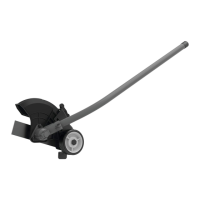
Edge Guide (Fig.E)
The edge guide is useful for cutting a straight path
alongsidewalks.
Cut Depth Adjustment (Fig.A, D)
WARNING: To reduce the risk of serious personal
injury, turn unit off and remove the battery pack
before making any adjustments or removing/
installing attachments or accessories, or prior to
cleaning. An accidental start‑up can causeinjury.
The front wheel can be adjusted to allow a deeper or
shallower cut, and to increase the life of the blade.
1. Wait for blade to come to completestop.
2. Removebattery.
3. Loosen the cut depthknob
2
.
4. Slide the wheel up or down to the desiredheight.
NOTE: Lowering the wheel will decrease the cutting
depth. Rasing the wheel will increase the cutting depth.
The recommend depth foredging is 1" (2.5cm).
NOTE: Thick overgrowth may drag on the guard. Reduce
the cut depth to the minimum to help reduce thiseffect.
5. Tighten knobfirmly.
Removing the Cutting Blade
1. Align the shaft bushing hole
15
with the locking rod
slot
16
and insert a screwdriver (not supplied) into the
bushinghole. Hold the screwdriver inposition.
2. While holding the screwdriver, remove the flange nut
12
by turning it counterclockwise with a 13mm wrench
(not supplied) as shown in Fig.C
3. Remove the blade spacer
11
and the blade
1
as shown
in Fig. C. Examine all pieces for damage and replace
ifnecessary.
Installing the New Cutting Blade
1. Install new blade
1
on shoulder of the blade cutter shaft
bushing
17
as shown in Fig.C.
2. Align the shaft bushing hole
15
with the locking rod
slot
16
and insert a screwdriver into the bushinghole.
3. Hold the screwdriver inposition.
4. Install the blade spacer
11
on the blade so that the wide
flat side faces theblade.
5. Install flange nut
12
with the flange against the blade
spacer
11
and securely tighten with a13mm wrench
(notsupplied).
6. Tighten nut counterclockwise against the blade while
holding the locking rod:
‑ If using a torque wrench and an 13mm socket
tighten to: 325‑335 in lb, 27‑ 28ft. lb, 37‑ 38Nm.
‑ Without a torque wrench, use a 13mm closed‑end
or socket wrench, turning the nut until the blade
retainer is snug against the shaft bushing. Ensure that
the blade is installed correctly, then rotate the nut an
additional 1/4 to 1/2 turncounterclockwise.
7. Remove the screwdriver from the locking rod slot
16
.
 Loading...