16
ENGLISH
Cutting Trim Molding and Other Frames
(Fig. S)
Sketch 2 in figureS shows a joint made by setting the mitre arm at 45° to
mitre the two boards to form a 90° corner. To make this type of joint, set
the bevel adjustment to zero and the mitre arm to 45°. Once again, position
the wood with the broad flat side on the table and the narrow edge against
the fence.
The two sketches in FigureS are for four-sided objects only. As the number
of sides changes, so do the mitre and bevel angles. The chart below gives
the proper angles for a variety of shapes, assuming that all sides are of
equallength.
NUMBER OF SIDES MITRE OR BEVEL ANGLE
4 45°
5 36°
6 30°
7 25.7°
8 22.5°
9 20°
10 18°
For a shape that is not shown in the chart, use the following formula: 180°
divided by the number of sides equals the mitre (if the material is cut
vertically) or bevel angle (if the material is cut laying flat).
Cutting Compound Mitres (Fig. T)
A compound mitre is a cut made using a mitre angle and a bevel angle at
the same time. This is the type of cut used to make frames or boxes with
slanting sides like the one shown in FigureT.
WARNING: If the cutting angle varies from cut to cut, check that the
bevel lock knob and the mitre lock handle are securely locked. These
must be locked after making any changes in bevel or mitre.
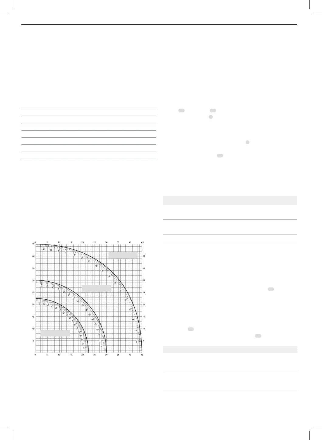
The chart shown below will assist you in selecting the proper bevel and
mitre settings for common compound mitre cuts.
Set this miter angle on saw
Angle of side of box (angle ”A”)
Set this bevel angle on saw
• Select the desired angle A (Fig.T) of your project and locate that angle
on the appropriate arc in the chart.
• From that point follow the chart straight down to find the correct bevel
angle and straight across to find the correct mitre angle.
• Set your saw to the prescribed angles and make a few trial cuts. Practise
fitting the cut pieces together.
Example: To make a 4-sided box with 26° exterior angles (Angle A, Fig.T),
use the upper right arc. Find 26° on the arc scale. Follow the horizontal
8 SIDED BOX
6 SIDED BOX
SQUARE BOX
intersecting line to either side to get mitre angle setting on saw (42°).
Likewise, follow the vertical intersecting line to the top or bottom to get the
bevel angle setting on the saw (18°). Always try cuts on a few scrap pieces
of wood to verify the settings on the saw.
Cutting Base Moulding (Fig. K1, K2, U)
To complete straight 90° cuts, position the wood against the fence and hold
it in place as shown in FigureU. Turn on the saw, allow the blade to reach
full speed and lower the arm smoothly through the cut.
Cutting Base Moulding from 76 mm up to 171 mm
High Vertically Against the Fence
DWS779 ONLY (FIG. K1)
NOTE: Move the saw blade in front of the base fence with the support
housing
58
and trunnion
59
73 mm apart, as shown in Figure K1.
Tighten the rail lock knob
7
to set the rails in place.
Position material as shown in FigureU.
All cuts should be made with the back of the moulding against the fence
and with the bottom of the moulding against the table.
After the cut is made, loosen the rail lock knob
7
.
DWS780 ONLY (FIG. K2)
NOTE: Use the slide lock lever
60
, shown in FigureK2, when cutting base
moulding measuring from 76 mm to 171 mm high vertically against the
fence.
Position material as shown in FigureU.
All cuts should be made with the back of the moulding against the fence
and with the bottom of the moulding against the table.
DWS779, DWS780
Inside Corner Outside Corner
Left side Mitre left 45°
Save left side of cut
Mitre right 45°
Save left side of cut
Right side Mitre right 45°
Save right side of cut
Mitre left 45°
Save right side of cut
Material up to 171 mm (6.75") can be cut as described above.
Cutting Crown Moulding (Fig. A1, V1, V2)
Your mitre saw is well suited to the task of cutting crown moulding. In
order to fit properly, crown moulding must be compound mitred with
extremeaccuracy.
Your mitre saw has special pre-set mitre latch points at 31.62° left and right
for cutting crown moulding at the proper angle and bevel stop pawls at
33.86° left and right. There is also a mark on the bevel scale
11
at 33.9°. The
chart below gives the proper settings for cutting crown moulding.
NOTE: Pretesting with scrap material is extremely important!
Instructions for Cutting Crown Moulding Laying
Flat and Using the Compound Features (Fig. V1)
1. Moulding should lay flat with the broad back surface down on the
sawtable
17
.
2. Place the top of the moulding against the fence
14
.
3. The settings below are for 45° sprung crown moulding.
Inside Corner Outside Corner
Left side Bevel left 30°
Mitre table set at right 35.26°
Save left end of cut
Bevel right 30°
Mitre table set at left 35.26°
Save left end of cut
Right side Bevel right 30°
Mitre table set at left 35.26°
Save right end of cut
Bevel left 30°
Mitre table set at right 35.26°
Save right end of cut