Do you have a question about the DeWalt DXGN14000 and is the answer not in the manual?
Indicates a hazardous situation which, if not avoided, will result in death or serious injury.
Indicates a hazardous situation which, if not avoided, could result in death or serious injury.
Indicates a hazardous situation which, if not avoided, could result in minor or moderate injury.
Notes provide additional info; alerts cannot eliminate hazards.
Manual aids dealer technicians and service personnel for product servicing.
Explains the 4 major components of a brushless generator.
Describes the 2-pole rotor, its function, and components.
Details the stator's three windings and their locations.
Explains circuit breaker function and protection against overload.
Covers startup, on-speed, field excitation, and output.
Guides users through diagnosing AC output problems.
Provides specific tests for diagnosing AC output issues.
Explains the 4 major components of a brush type generator.
Details the stator's three windings and their locations.
Describes the brush holder, brushes, and their connection.
Explains the function of the voltage regulator.
Covers startup, on-speed, field excitation, and output.
Guides users through diagnosing AC output problems.
Provides specific tests for diagnosing AC output issues.
Guides users on using flow charts for engine diagnostics.
Flowchart for diagnosing a non-pulling recoil cord.
Flowchart for diagnosing rough running engines.
Flowchart for engines that crank but don't start.
Flowchart for diagnosing erratic engine idle.
Flowchart for engines that do not crank.
Flowchart for recoil cord issues.
Procedure to check the generator's fuse.
Procedure to inspect battery and cables.
Procedure to check voltage at starter contactor.
Explains and tests the start-run-stop switch function.
Procedure to test the OFF-ON switch.
Lists conditions affecting starter performance and procedure.
Procedure to test engine ignition spark using a tester.
Procedure for inspecting and replacing spark plugs.
Procedure for checking fuel supply and carburetor issues.
Procedure to check choke for carburetion problems.
Explains valve adjustment and provides specifications.
Procedure for checking engine compression.
Details how to check compression and common causes of poor compression.
Describes the ignition system and tests the ignition coil.
Procedure to check the flywheel magnet.
Checks flywheel magnetism and key.
Checks the integrity of the shutdown wire.
Explains governor function and adjustment.
Procedure to test the engine recoil function.
Procedure to test engine function by turning over.
Explains and tests the battery charger function.
Procedure for testing the low idle control system.
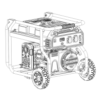
Introduces the general disassembly process for the generator.
Provides an exploded view of the generator components.
Directs users to online resources for wiring diagrams.
Provides the electrical schematic for DXGN4500.
Provides the electrical schematic for DXGN6000.
Provides the electrical schematic for DXGN7200.
Provides the electrical schematic for DXGN14000.
Provides the electrical schematic for DXGNR5700.
Provides the electrical schematic for DXGNR7000.
| Brand | DeWalt |
|---|---|
| Model | DXGN14000 |
| Category | Portable Generator |
| Language | English |