11
ENGLISH
Lanyard Connection (Fig. A, L)
Optional Accessory
Safety Warnings Specific for Use At Height
WARNING:
If the tool is dropped for any reason the lanyard connection
must be inspected and properly serviced prior to re‑use. The
lanyard connection is designed to stretch to absorb the shock
of a drop. Any permanent stretch to the connection exposing
the red marked internal coils indicates it has been compromised
and must be serviced prior toreuse.
• Do not use hang hook as lanyard attachmentpoint.
Active Vibration Control (Fig. A)
For best vibration control, hold the tool with one hand on the
main handle
6
and the other hand on the side handle
1
. Apply
just enough pressure so the Active Vibration Control
10
in the
rear handle are halfway depressed. The hammer only needs
enough pressure to engage the internal active vibration control.
Applying too much pressure will not make the tool drill faster
and active vibration control will notengage.
Electronic Overload Protection
If the drill bit becomes jammed, the power to the drill spindle
will be interrupted by the activation of the electronic overload
protection. To reactivate the power to the drive spindle, the
tool's trigger should be released and then depressed. Due to the
resulting forces, always hold the tool with both hands and take
a firmstance.
To Install the Battery Pack into the Tool Handle
1. Align the battery pack
8
with the rails inside the tool’s
handle (Fig. J).
2. Slide it into the handle until the battery pack is firmly seated
in the tool and ensure that you hear the lock snap intoplace.
To Remove the Battery Pack from the Tool
1. Press the release button
9
and firmly pull the battery pack
out of the toolhandle.
2. Insert battery pack into the charger as described in the
charger section of thismanual.
Fuel Gauge Battery Packs (Fig.B)
Some DeWALT battery packs include a fuel gauge which
consists of three green LED lights that indicate the level of
charge remaining in the batterypack.
To actuate the fuel gauge, press and hold the fuel gauge
button
14
. A combination of the three green LED lights will
illuminate designating the level of charge left. When the level
of charge in the battery is below the usable limit, the fuel gauge
will not illuminate and the battery will need to berecharged.
NOTE: The fuel gauge is only an indication of the charge left on
the battery pack. It does not indicate tool functionality and is
subject to variation based on product components, temperature
and end‑userapplication.
Inserting and Removing the Battery Pack
from the Tool (Fig. J)
NOTE: Make sure your battery pack
8
is fullycharged.
ASSEMBLY AND ADJUSTMENTS
WARNING: To reduce the risk of serious personal
injury, turn tool off and disconnect battery pack
before making any adjustments or removing/
installing attachments or accessories. An accidental
start‑up can causeinjury.
WARNING: Use only DeWALT battery packs andchargers.
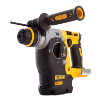
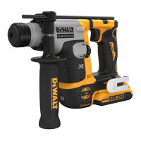
Description (Fig. A)
WARNING: Never modify the power tool or any part of it.
Damage or personal injury couldresult.
1
Side handle
2
Depth rod
3
Trigger switch
4
Forward/reverse control button (Lock‑off button)
5
Mode selector
6
Main handle
7
Worklight
8
Battery pack
9
Battery release button
10
Active Vibration Control
11
Utility hook
12
Lanyard attachment point
Intended Use
This heavy‑duty cordless rotary hammer is designed for
professional concrete, wood and metal drillingapplications.
DO NOT use under wet conditions or in the presence of
flammable liquids orgases.
This heavy‑duty cordless rotary hammer is a professional
powertool.
DO NOT let children come into contact with the tool.
Supervision is required when inexperienced operators use
thistool.
• Young children and the infirm. This appliance is not
intended for use by young children or infirm persons
withoutsupervision.
• This product is not intended for use by persons (including
children) suffering from diminished physical, sensory or
mental abilities; lack of experience, knowledge or skills
unless they are supervised by a person responsible for their
safety. Children should never be left alone with thisproduct.
Date Code Position (Fig.B)
The date code
13
, which also includes the year of manufacture,
is printed into thehousing.
Example:
2021XX XX
Year and Week of Manufacture
 Loading...