13
ENGLISH
Guards
CAUTION: Guards must be used with all grinding
wheels, cutting wheels, sanding flap discs, wire
brushes, and wire wheels. The tool may be used
without a guard only when sanding with conventional
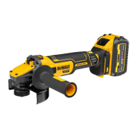
sanding discs. Refer to Figure A to see guards provided
with the unit. Some applications may require purchasing
the correct guard from your local dealer or authorized
servicecentre.
NOTE: Edge grinding and cutting can be performed with Type
27wheels designed and specified for this purpose; 6.35 mm
thick wheels are designed for surface grinding while thinner
Type 27wheels need to be examined for the manufacturer's
label to see if they can be used for surface grinding or only
edge grinding/cutting. A Type 1guard must be used for any
wheel where surface grinding is forbidden. Cutting can also be
performed by using a Type41wheel and a Type 1guard.
NOTE: See the Accessory Chart to select the proper guard /
accessorycombination.
Mounting and Adjusting the One‑Touch
TM
Guard
(Fig.F)
WARNING: To reduce the risk of serious personal
injury, turn tool off and disconnect battery pack
before making any adjustments or removing/
installing attachments or accessories. An accidental
start‑up can causeinjury.
Adjusting the Guard
For guard adjustment, the guard release lever
9
engages
one of the alignment holes
15
on the guard collar using a
ratchetingfeature.
The engaging face is slanted and will ride over to the
next alignment hole when guard is rotated in a clockwise
direction (spindle facing user) but self‑locks in the
anti‑clockwisedirection.
Mounting the Guard (Fig.F)
1. Press the guard release lever
9
.
Rotating the Gear Case (Fig. D)
To improve user comfort, the gear case will rotate 90° for
cuttingoperations.
1. Remove the four corner screws attaching the gear case to
motorhousing.
2. Without separating the gear case from motor housing,
rotate the gear case head to desiredposition.
NOTE: If the gear case and motor housing become separated
by more than 3.17 mm, the tool must be serviced and
re‑assembled by a DeWALT service center. Failure to have the
tool serviced may motor and bearingfailure.
3. Reinstall screws to attach the gear case to the motor
housing. Tighten screws to 12.5 in.‑lbs. torque.
Overtightening could cause screws tostrip.
Screw the side handle
5
tightly into one of the holes on either
side of the gear case. The side handle should always be used to
maintain control of the tool at alltimes.
Attaching Side Handle (Fig. C)
WARNING: Before using the tool, check that the handle is
tightenedsecurely.
Inserting and Removing the Battery Pack
from the Tool (Fig. B)
NOTE: Make sure your battery pack
10
is fullycharged.
To Install the Battery Pack into the Tool Handle
1. Align the battery pack
10
with the rails inside the tool’s
handle (Fig. B).
2. Slide it into the handle until the battery pack is firmly seated
in the tool and ensure that you hear the lock snap intoplace.
To Remove the Battery Pack from the Tool
1. Press the release button
11
and firmly pull the battery pack
out of the toolhandle.
2. Insert battery pack into the charger as described in the
charger section of thismanual.
Fuel Gauge Battery Packs (Fig.C)
Some DeWALT battery packs include a fuel gauge which
consists of three green LED lights that indicate the level of
charge remaining in the batterypack.
To actuate the fuel gauge
19
, press and hold the fuel gauge
button. A combination of the three green LED lights will
illuminate designating the level of charge left. When the level
of charge in the battery is below the usable limit, the fuel gauge
will not illuminate and the battery will need to berecharged.
NOTE: The fuel gauge is only an indication of the charge left on
the battery pack. It does not indicate tool functionality and is
subject to variation based on product components, temperature
and end‑userapplication.
ASSEMBLY AND ADJUSTMENTS
WARNING: To reduce the risk of serious personal
injury, turn tool off and disconnect battery pack
before making any adjustments or removing/
installing attachments or accessories. An accidental
start‑up can causeinjury.
WARNING: Use only DeWALT battery packs andchargers.
to restarttool. The tool will power off each time the current
load reaches the overload current value (motor burn‑up point).
If continued overload shutdowns occur, apply less force/
weight on the tool until the tool will function without the
overloadengaging.
Soft Start Feature
The soft start feature allows a slow speed build‑up to avoid an
initial jerk when starting. This feature is particularly useful when
working in confinedspaces.
Anti‑vibration Side Handle
The anti‑vibration side handle offers added comfort by
absorbing the vibrations caused by thetool.
 Loading...
