Do you have a question about the Dewetron TRION Series and is the answer not in the manual?
Details the application of TRION/TRION3 modules for measuring physical/electrical variables.
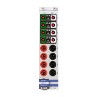
Explains how module names contain information about type, channels, resolution, and connector.
Contains warning and safety instructions for user. Faultless operation depends on observation.
Read manual, use within specifications, expert installation, no self-service, observe local laws, avoid damaged equipment.
Keep away from live circuits, do not touch exposed parts, avoid higher voltage than specified.
Product for industrial use, avoid residential use due to interference, acclimatize unpowered, avoid wet/adverse conditions.
Compliance with FCC limits for Class A products, avoiding harmful radio interference.
Product meets factory standards; user must follow security advice and warnings.
Defines WARNING, CAUTION, NOTICE, INFORMATION icons and their meanings.
Explains symbols used in the manual, like warning, hazardous voltage, chassis terminal, current types.
Information on product environmental impact and end-of-life handling, recycling guidelines.
Warns against installing IT/MIS software on DEWETRON systems due to interference.
Specific warranty terms can be obtained from local sales and service office.
Information subject to change without notice; DEWETRON not liable for errors.
Refers to the page bottom for printing version.
Information on TRION module compatibility with OXYGEN versions and hardware.
Overview of hardware compatibility between DEWE2/3 systems and TRION3 modules.
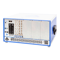
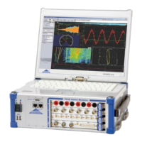
General overview of DEWE2/DEWE3 system architectures: Power analyzer, All-in-one, Mainframe, Front-end.
Details on DEWE2/DEWE3 all-in-one instrument models and their TRION module slots.
Details on DEWE2/DEWE3 mainframe models and their TRION module slots.
Details on DEWE2 front-end models and their TRION module slots.
Details on DEWE2/DEWE3 power analyzer models and their TRION module slots.
Details on DEWE3 rack mount models and their TRION module slots.
Specifies operating temperature, storage temperature, and humidity for TRION(3) modules.
Step-by-step guide on how to install a TRION module into a chassis, including ESD precautions.
Explains the STAR-slot functionality for timing/sync/GPS modules and other TRION(3) modules.
Shows the division of slots into segments for DEWE3-RMx devices.
Shows the division of slots into segments for DEWE2-M13/M13s/M18 devices.
Step-by-step guide on how to remove a TRION(3) module from a chassis.
Describes the delta-sigma A/D converters and sampling process for TRION-2402 series.
Explains the function of the anti-aliasing filter and the Nyquist frequency to prevent aliasing.
Discusses the combination of analog and digital IIR filters in TRION-2402 series.
Details the 18-bit 5 MS/s ADC and channel phase shift for TRION(3)-18xx-MULTI series.
Overview table of different TRION(3)-18xx-MULTI boards and their specifications.
Describes the highspeed mode for TRION3-1850-MULTI series and data transfer.
Explains oversampling mode for TRION(3)-18xx-MULTI series, improving resolution.
Discusses the combination of analog and digital filters in TRION(3)-18xx-MULTI series.
Compares SAR converters to delta-sigma converters regarding step response.
Recommends sample rate settings and filter choices for TRION(3)-18xx-MULTI aliasing protection.
Details the 18-bit 10 MS/s ADC and signal bandwidth for TRION(3)-18xx-POWER series.
Overview table of TRION(3)-18xx-POWER series boards and their specifications.
Describes the highspeed mode for TRION(3)-18xx-POWER series and data transfer.
Explains oversampling mode for TRION(3)-18xx-POWER series, increasing resolution.
Details the 16-bit 2 MS/s ADC and channel phase error for TRION-1620 series.
Overview table of TRION-16xx series boards and their specifications, including IEPE and TEDS.
Describes highspeed mode for TRION-1620 series and analog calibration.
Explains oversampling mode for TRION-1620 series, increasing resolution.
Discusses analog and digital filters in TRION-16xx series, and their use in highspeed mode.
Compares SAR converters to delta-sigma converters regarding step response.
Recommends sample rate settings and filter choices for TRION-16xx aliasing protection.
Explains that TRION-1620 series computes calculations on-board, freeing host CPU.
Provides an overview of DEWE chassis clocking and synchronization functions.
Explains how timing information is distributed via TRION-SYNC-BUS and AD clock generation.
Discusses how system time base affects measurements and timing accuracy.
Overview table comparing synchronization types and their accuracies.
Describes synchronizing two DEWE2/DEWE3 systems using TRION-SYNC-BUS.
Explains the need for absolute time synchronization with external events using GNSS or PTP.
Table detailing synchronization types, accuracy, distance, and recommendations.
Detailed specifications including input channels, sampling rate, data transfer, ADC type, input ranges, accuracy.
Specifies IEPE® excitation current and compliance voltage.
Discusses advantages of module isolation like high common mode voltage and input protection.
Recommends connecting system to structural ground for best signal-to-noise ratio.
Provides schematics for voltage, current, and sensor connections with software settings.
Describes functions like Short, Self test, IEPE, Counter function for TRION-16xx series.
Detailed specifications including input channels, sampling rate, accuracy, input noise, and isolation.
Discusses advantages of module isolation like high common mode voltage and input protection.
Recommends connecting system to structural ground for best signal-to-noise ratio.
Provides schematics for voltage and current connections with software settings.
Describes functions like Short, Self test, Isolation, Ground connection for TRION-16xx series.
Covers input types, ranges, supported sensors, sampling rate, resolution, and power consumption.
Details specifications of the input amplifier, including voltage input accuracy, drift, linearity, and impedance.
Describes excitation voltage, current, protection, and IEPE® excitation for the module.
Explains supported bridge types, internal completion resistors, and bridge features.
Details analog output specifications, modes, accuracy, and bandwidth.
Specifies CAN interface details: specification, physical layer, termination, and bus pin fault protection.
Describes counter functionality, modes, timebase, filter, and connection.
Highlights advantages of isolated inputs: high common mode voltage, overcurrent protection, ground loop elimination.
Explains that amplifier parameters like gain and excitation are programmable per channel.
Describes the sensor balance function for automatically removing sensor offset.
Mentions support for three different quarter bridge completions (120, 350, 1000 Ω).
Explains function for checking Quarter Bridge wiring and determining sensitivity loss due to cable resistance.
Describes using REF input for routing known calibrated signals to analog inputs for checks.
Details counter input support, routing, and available functions like event counting and frequency measurement.
Details self-test functions for verifying board features and analog accuracy.
Explains base section test results and analog test section for channels and ranges.
Detailed specifications including input channels, ADC, input ranges, accuracy, and power consumption.
Lists input channels for TRION-2402-MULTI-4-D and -8-L0B variants.
Lists input ranges for Voltage, IEPE, Bridge, Resistance, and Current.
Details voltage input accuracy across different frequency ranges.
Describes excitation voltage range, accuracy, drift, and current limit.
Lists supported sensor types like bridge sensors, potentiometer, resistance, and IEPE®.
Specifies bridge resistance values and shunt calibration details.
Describes the analog anti-aliasing filter selection based on sample rate.
Specifies channel-to-channel phase mismatch values.
Discusses advantages of isolation: high common mode voltages, overcurrent protection, ground loop elimination.
Explains that amplifier parameters like gain and excitation are programmable per channel.
Describes amplifier balance for eliminating internal amplifier offsets and compensating drift.
Explains sensor balance function for automatically removing sensor offset up to 400% of range.
Describes function to switch inputs to half bridge reference for determining absolute sensor offset.
Describes using external signal via REF input for voltage input calibration.
Describes the CAN bus interface and its application for connecting compatible devices.
Detailed specifications including input channels, sampling rate, resolution, input ranges, accuracy, and excitation.
Lists input channels for TRION-2402-dSTG-8-RJ, -8-D, -6-L1B, and -8-L0B variants.
Specifies sampling rate per channel for the TRION-2402-dSTG module.
Lists input ranges for Voltage, Bridge, IEPE, Resistance, and Current.
Details voltage input accuracy across different frequency ranges.
Describes excitation voltage range, accuracy, drift, and current limit.
Lists supported sensor types like bridge sensors, potentiometer, resistance, and IEPE®.
Specifies bridge resistance values and shunt calibration details.
Describes the analog anti-aliasing filter selection based on sample rate.
Specifies channel-to-channel phase mismatch values.
Explains that amplifier parameters like gain and excitation are programmable per channel.
Details self-test functions for verifying board features, voltage amplifier path, and sensor power supply.
Refers to A/D conversion chapter for bandwidth and filtering details.
Lists available input high pass filters for AC coupling.
Explains TEDS communication and support for common TEDS chips.
Detailed specifications including input channels, sampling rate, resolution, input ranges, accuracy, and input coupling.
Lists input channels for TRION-2402-dACC-8-SMB and -6-BNC variants.
Specifies sampling rate per channel for the TRION-2402-dACC module.
Lists input ranges for Voltage, IEPE, Resistance, and Current.
Details voltage input accuracy across different frequency ranges.
Describes available input coupling options (DC, AC).
Describes short circuit and open sensor detection with LED indication for IEPE®.
Describes counter input support and available functions like event counting, period measurement, etc.
Explains that amplifier parameters like gain and excitation are programmable per channel.
Lists available input high-pass filters for AC coupling.
Details self-test functions for checking analog input path by applying voltage.
Detailed specifications including input channels, sampling rate, resolution, input ranges, accuracy, and protection.
Lists input channels for TRION-2402-V-4-B and -8-B variants.
Lists input ranges for Voltage and Current.
Details voltage input accuracy across different frequency ranges.
Specifies isolation voltage values.
Details overvoltage protection limits for different input ranges.
Specifies input impedance values for different ranges.
General specifications including input channels, sampling rate, resolution, phase mismatch, and filters.
Covers input channels, sampling rate, resolution, phase mismatch, filters, data buffer, and power consumption.
Details specifications for fixed high-voltage inputs, including input range, resolution, accuracy, and protection.
Lists supported TRION-SUB modules for expanding input capabilities.
Covers fixed high-voltage input specifications like sampling rate, resolution, input range, accuracy, and protection.
Details specifications for fixed high-voltage inputs, including input range, resolution, accuracy, and protection.
Illustrates connection ports for fixed high-voltage inputs and interchangeable sub-modules.
Details power specifications, including active power accuracy, influence of power factor, and filter characteristics.
Lists available TRION-SUB modules that can be combined for various input configurations.
General specifications including input channels, sampling rate, input specifications, phase mismatch, filters, and power consumption.
States that the module has up to 8 channels with modular voltage and current inputs.
Refers to TRION sub-modules for detailed input specifications.
Describes filter order and characteristics for the low-pass filter.
Explains filter delay compensation for selected filters.
Specifies power consumption with and without sensor supply.
Details sensor supply voltage and current for TRION-POWER-SUB-dLV-xV modules.
Lists supported TRION-SUB modules that can be combined for various input configurations.
Specifies number of channels, compatibility, overvoltage protection, and connector for digital I/O.
Describes functionality, compatibility, overvoltage protection, and connector for Sync OUT.
Details number of channels, counter modes, compatibility, resolution, time base, frequency, and protection.
Describes functionality, compatibility, overvoltage protection, and connector for AUX terminal.
Specifies typical power consumption, temperature range, and weight.
Lists supported synchronization input modes: PTP/IEEE 1588, GPS, IRIG, PPS.
Lists module features: frequency output, advanced counter, and digital I/O.
Specifies PTP/IEEE 1588 settings including IP mode, protocol, delay mechanism, and IP address method.
Details RJ-45 Ethernet connection for synchronization only.
Specifies the programmable correction limit for synchronization.
Details GPS specifications: supported signals, position accuracy, refresh rate, time to first fix, and velocity accuracy.
Details IRIG input specifications: supported codes, compatibility, ratio, and compatibility for DC code.
Specifies number of channels, compatibility, and overvoltage protection for digital I/O.
Details number of channels, counter modes, input signal compatibility, resolution, time base, frequency, and protection.
Describes functionality, compatibility, overvoltage protection, and connector for AUX terminal.
Details GPS specifications: supported signals, position accuracy, refresh rate, time to first fix, and velocity accuracy.
Specifies PTP/IEEE 1588 settings including IP mode, protocol, delay mechanism, and IP address method.
Explains position smoothing filter settings for enabling, disabling, or resetting Pseudorange/Delta-Phase.
Explains how SBAS dictates receiver tracking and use of correction data for accuracy.
Configures the source of the velocity that is used.
Detailed specifications including input channels, counter modes, input signal characteristic, isolation, and counter resolution.
Lists counter modes like waveform timing, sensor modes, and event counting.
Explains programmable trigger and retrigger levels for each input channel.
Describes the digital filter function and its gate time settings.
Details isolation of digital inputs and power supply specifications.
Explains the possibility to digitally invert input signals.
Explains event counting by counting pulses on input A/B at acquisition clock.
Explains gated event counting where counting is gated by Input B's state.
Explains measuring period time of signal on Input A using internal time base.
Explains measuring pulse width of signal on Input A using internal time base.
Explains measuring separation between edges of Input A and Input B.
Describes motion encoder channels (A, B, Z) and different decoding types (X1, X2, X4).
Explains frequency measurement using period time or counter values.
Detailed specifications including input channels, input modes, sampling rate, and input signal characteristic.
Specifies 48 isolated digital inputs.
Specifies sampling rate as 3 MS/s.
Details compatibility, configuration, input levels, current, propagation delay, bandwidth, and protection.
Specifies isolation voltage between channels and to chassis.
Specifies the input connector type.
Specifies input channels, CAN specification, physical layer, listen only mode, termination, isolation, and protection.
Lists 4 input channels with D-SUB-9 connector.
Specifies CAN 2.0B.
Describes Highspeed, low speed, and single wire physical layers.
Explains the need for termination and module's programmable termination resistance.
Specifies bus pin fault protection level.
Specifies ESD protection level.
Describes highspeed CAN bus topology, cable lengths, and recommended termination resistors.
Discusses allowable cable lengths and characteristics for highspeed CAN bus.
Specifies I/O connector, communication standard, isolation voltage, compatible chassis, and operating system.
Compares TRION-ARINC429 and TRION-MIL1553 specifications for input channels, connector, baud rate, power consumption, and software support.
Lists input channels for ARINC429 and MIL1553 modules.
Specifies connector types for ARINC429 and MIL1553.
Lists supported baud rates for TRION-ARINC429.
Specifies power consumption for different channel configurations.
Lists OXYGEN software capabilities for decoding signals, visualization, and export.
Specifies configuration, voltage rails, and connector for the power supply module.
Details power limits for +15 V / -15 V and +9 V supply rails with LED indication.
Overview table of TRION sub-modules with type, range, bandwidth, and isolation.
Specifications for TRION-SUB-600V module: range, resolution, accuracy, and connector.
Specifications for TRION-SUB-5V module: range, resolution, accuracy, and connector.
Specifications for TRION-POWER-SUB-CUR-20A-1B module: range, resolution, accuracy, and SNR.
Specifications for TRION-POWER-SUB-CUR-2A-1B module: range, resolution, accuracy, and SNR.
Specifications for TRION-POWER-SUB-CUR-1A-1B module: range, resolution, accuracy, and SNR.
Specifications for TRION-POWER-SUB-CUR-02A-1B module: range, resolution, accuracy, and SNR.
Specifications for TRION-POWER-SUB-dLV-5V module: range, resolution, accuracy, and SNR.
Specifications for TRION-POWER-SUB-dLV-1V module: range, resolution, accuracy, and SNR.
Specifications for TRION-POWER-SUB-dLV-1 module: range, resolution, accuracy, and SNR.
Details cleaning procedures for chassis exterior/interior and filter foam.
Provides instructions for cleaning surfaces and interior with dry lint-free cloth or air.
Covers Windows and antivirus/security software updates, and system software updates.
Advises contacting DEWETRON for software packages and mentions BIOS protection.
Information on DEWETRON training courses offered at various locations.
Explains the need for regular calibration and DEWETRON's calibration process.
Provides contact information for DEWETRON support and local distributors.
Guidance on how to get DEWETRON products serviced or repaired, including RMA policy.
General information on signal analysis terms.
Defines fundamental frequency as the lowest frequency of a periodic test-signal.
Defines harmonic frequencies as multiples of the fundamental frequency.
Describes frequency components appearing due to electrical components, not harmonics.
Includes all voltage and frequency components present during measurement but not in the ideal signal.
Defines DC component as a spur with 0 Hz frequency.
Provides general information about testing procedures and definitions of SNR, SFDR, THD, and CMRR.
Details test setup, filter settings, input signals, and function generators used.
Defines SNR and provides formulas for calculating it based on ACRMS.
Defines SFDR as the range between signal amplitude and the highest spur, excluding harmonics and DC.
Defines ENOB as a characteristic relating SNR to bits of resolution, calculated from SNR.
Defines THD as the RMS value of the first five harmonics compared to the fundamental frequency.
Defines CMRR as common-mode rejection ratio, filtering out input signals common to both inputs.
Explains phase mismatch values in nanoseconds and their conversion to degrees.
Explains technical terms related to measurement inputs and safety.
Indicates the highest voltage for input pin to reference potential without isolation breakdown.
Defines input range as the highest possible value displayable, similar to a dial instrument limit.
Defines allowable application scope based on IEC/EN 61010-2-30 standards.
Indicates highest possible voltage before overloading input protection circuit.
| Category | Measuring Instruments |
|---|---|
| Series | TRION |
| Modules | Various TRION modules available, supporting different measurement types |
| Channels | Scalable, depending on the number and type of TRION modules used |
| Resolution | Up to 24-bit, depending on the module |
| Input Types | Voltage, Current, Thermocouple, RTD, Strain Gauge, IEPE |
| Interface | USB, EtherCAT |
| Operating Temperature | -20 °C to +50°C |
| Dimensions | Varies depending on the carrier system and number of modules |
| Weight | Varies by module |