XR-RTD8
No. Element
1. RTD input connectors
1. 3. Shield: Chassis GND
2. 4.
2.
INFORMATIONChange from
RS-485 to CAN mode on page 30
3. State LED
4.
connector
connector
1. 3.
2. 4. GND
1. 3.
2. 4. GND
Tab. 2: Connecons and ports XR-RTD8
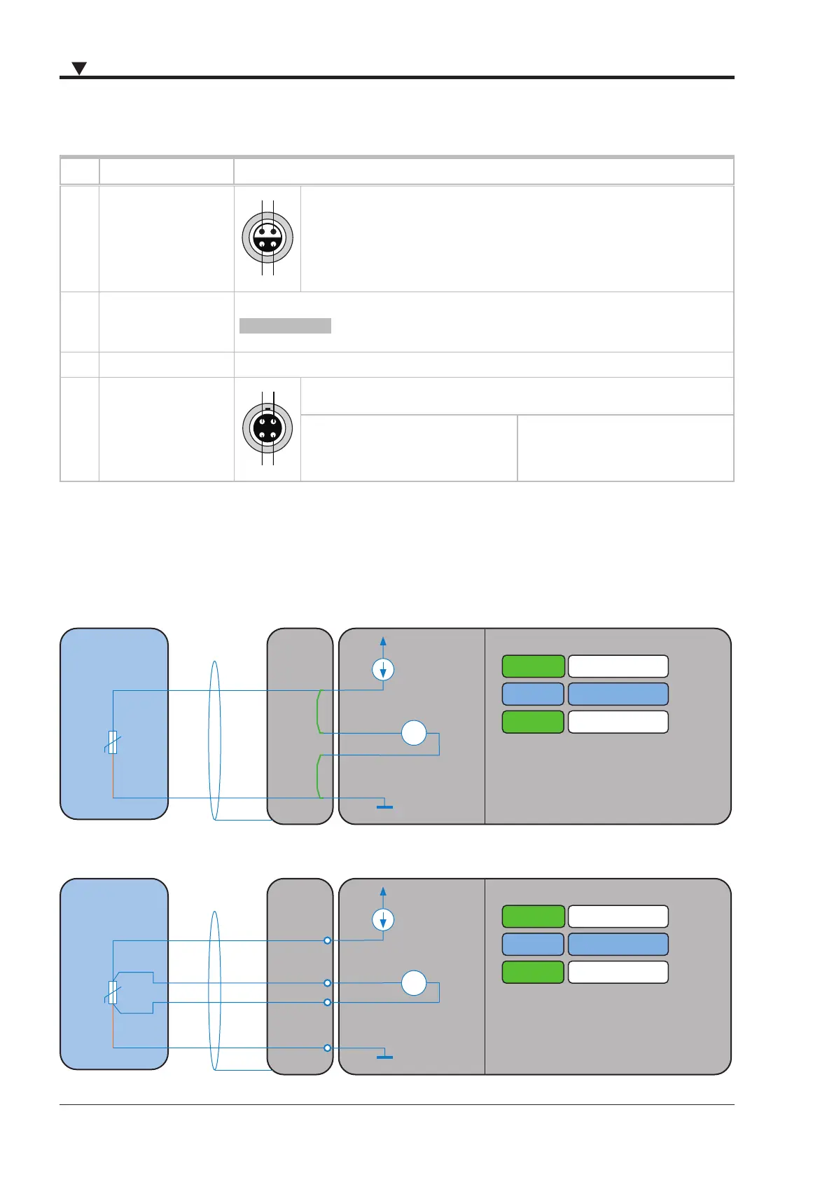
Sensor connection
2-wire connection
LEMO
CONNECTOR
Mode
3
4
Range
Sensor type
Temperature
RTD
XR-RTD8
V
IN
4-wire connection
LEMO
CONNECTOR
Mode
3
4
Range
Sensor type
Temperature
V
IN
RTD
XR-RTD8
 Loading...