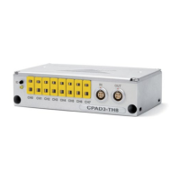
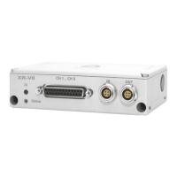
XR-V8
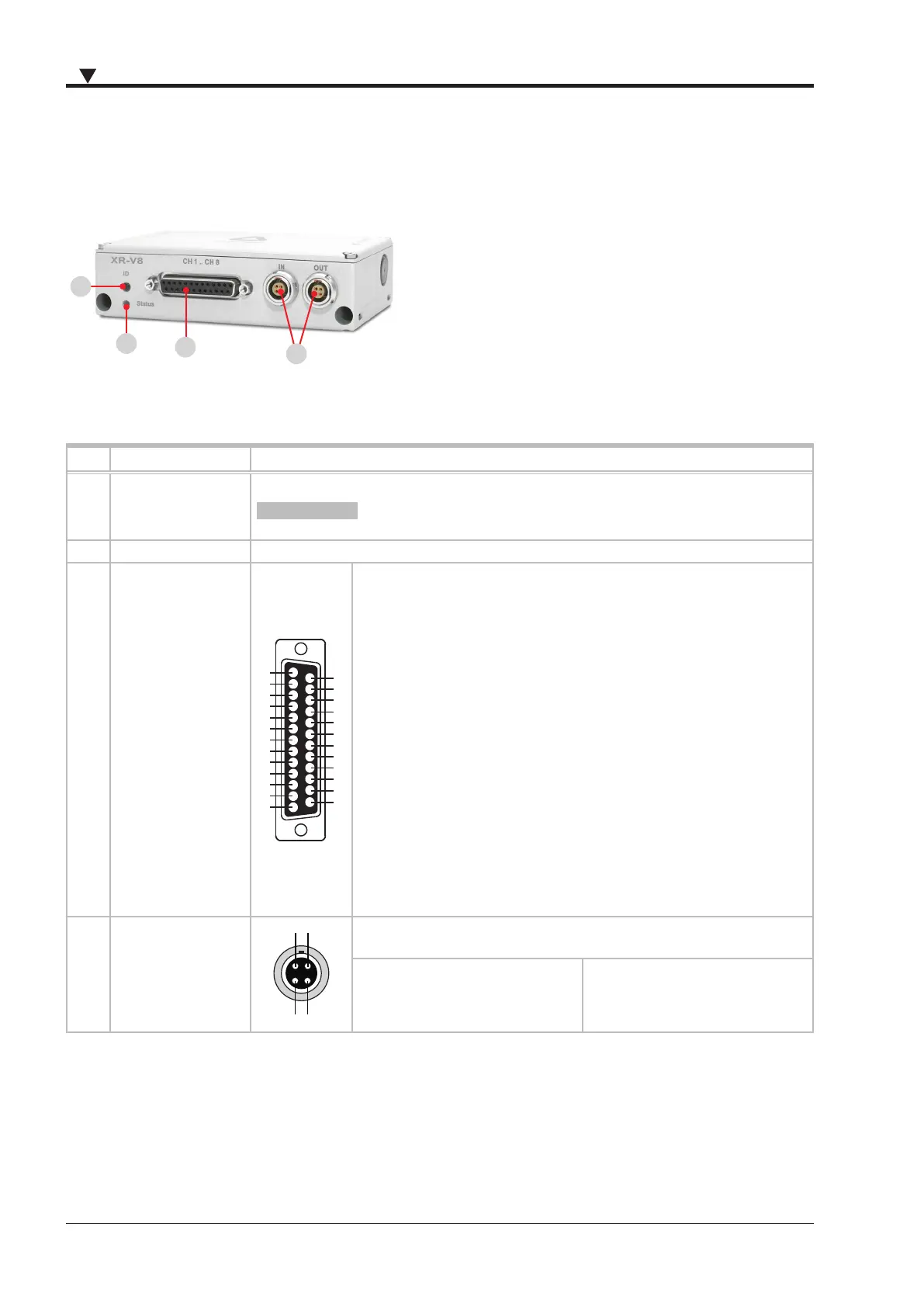
Connection
3
2
1
4
Fig. 4: Connecons XR-V8
No. Element
1.
INFORMATIONChange from RS-
485 to CAN mode on page 30
2. Status LED
3.
nector
nector
25
24
23
22
21
20
19
18
17
16
15
14
13
12
11
10
9
8
7
6
5
4
3
2
1
1.
2.
3.
4.
5.
6.
7.
8.
9.
10.
11.
12.
13.
14.
15.
16.
17.
18.
19.
20.
21.
22. GND
23.
24.
25.
4. XR interface connec
tor
connector
1. 3.
2. 4. GND
1. 3.
2. 4. GND
Tab. 4: Connecons and ports XR-V8
 Loading...