Dewhot | Gas geyser manual
Page 10 of 12
Dewhot | Gas geyser manual
Page 11 of 12
Safety instructions:
If you smell gas:
• Turn off the gas cock.
• Do not operate any electrical switches.
• Do not telephone from inside the
danger area.
• Open windows and ventilate room.
• From outside, call the gas company and
your approved installer.
Do not use or store easily combustible
materials in the vicinity of the appliance.
Installation and Operating
Instructions
Installation and servicing of the appliance
may only be carried out by a registered
gas installer.
The appliance should be regularly
maintained in order to ensure that it
remains in perfect and safe working order.
If there is a risk of freezing, the appliance
must be switched off and drained. If the
appliance has not been drained during a
cold spell then when it is switched on again
check that it produces hot water. If problems
occur, contact your installer
Function
This water heater is fitted with automatic
electronic ignition that provides for easy
commissioning. All that is required is to
switch on a hot water tap.
The appliance will then ignite automatically
as soon as a hot water tap is turned on.
The igniters fire (tick, tick, tick sound) the
gas solenoid opens (clack sound) and then
a second later the burners ignite and the
ingniters stop firing. When you switch the
water off the gas solenoid closes (faint
thud noise).
The appliance is substantially more
economical because there is no pilot flame
and only remains lit while water flows, thus
no further gas is used, in contrast with
conventional appliances which have a pilot
flame that remains alight permanently.
Air in the gas pipe when the appliance is
commissioned must be vented, this can
cause ignition failure. In such cases,
the hot water tap should be turned off and
then on again so that the appliance repeats
the ignition cycle. The procedure should be
repeated as necessary until the gas pipe is
purged of air and ignition is achieved.
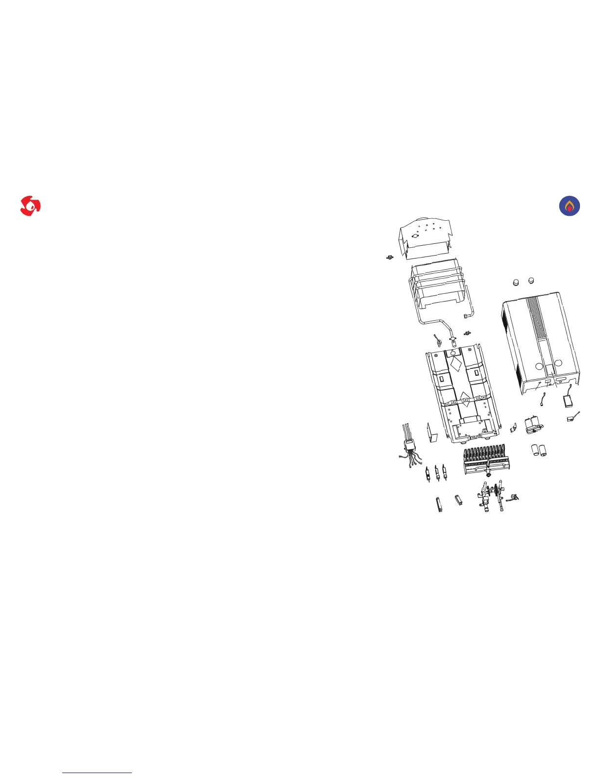
1. Chimney
2. Flue sensor
3. Heat exchanger
4. Thermostat
5. Temperature Probe
6. Base plate
7. Impluse
8. Impulse bracket
9. Ignition pin
10. Ignition pin
11. Flame sensor pin
12. Burner
13. Valve left bracket
14. Valve right bracket
15. Water and Gas valve
16. Micro switch
17. Battery
18. Battert
19. Battery box bracket
20. Battery box
21. Switch off for cold
22. Battery indicator
23. LED display (Optional
models)
24. Front cover
25. Adjustment knob
26. Adjustment knob
a. Hot water outlet
b. Gas inlet
c. Cold water inlet
d. Flue pipe joint
1
2
3
4
5
6
7
8
9
10 11
12
13
14
15
16
17
18
19
20
21
22
22
21
23
24
25
d
26
23
b
c
a