Do you have a question about the DewStop FS-875 and is the answer not in the manual?
General cautions for installation, including power supply, indoor use, load ratings, local codes, ground connection, and fan type.
Essential safety steps: turn off power at the breaker and test before starting any wiring.
Step-by-step guide for wiring, connecting wires, and ensuring proper grounding.
Instructions for tucking wires and fastening the control unit into the wall enclosure.
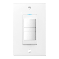
Description of the Blue LED Light, Light ON/OFF, and Fan ON/OFF controls.
Instructions on how to adjust countdown and Minutes Per Hour (MPH) timer settings using the included tool.
Explanation of how the countdown timer operates to automatically shut off the fan after a set period.
Details on the MPH timer for maintaining indoor air quality by running the fan periodically.
How the countdown and MPH timers work together, including manual overrides and credits.
Procedure to test the fan and light functions after installation and setting adjustments.
Details of the two-year limited warranty, including coverage, limitations, and service request procedures.
The DewStop FS-875/FS-3875 Adjustable Fan Timer is a sophisticated control designed to manage ventilation in bathrooms, laundry rooms, sun rooms, or spa rooms, ensuring optimal indoor air quality. This device integrates two distinct timers: a countdown timer and a Minutes Per Hour (MPH) timer, which work in conjunction to provide comprehensive ventilation control.
The countdown timer allows users to set the fan to run for a specific duration, ranging from 5 to 60 minutes. This timer is manually activated whenever the fan is turned on. It's particularly useful for situations requiring immediate ventilation, such as after a shower or bath, to quickly remove moisture and odors. The recommended usage for this timer involves adding the time it takes to shower with the time it takes for the bathroom to dry off afterward, and setting that total as the timer duration.
Complementing the countdown timer is the Minutes Per Hour (MPH) timer, which operates on a recurring schedule to maintain consistent air quality. This timer can be set to run the fan for a specified number of minutes every hour, with settings ranging from 0 to 60 minutes. For instance, if set to "10," the fan will activate for 10 minutes every hour. A setting of "0" means the MPH timer will never turn on, while "60" means the fan will run continuously. The MPH timer is designed to help comply with local indoor air quality standards, such as ASHRAE 62.2, by regularly expelling stale air.
A key feature of this device is how the two timers interact through a "credits" system. The MPH timer is programmed to recognize manual fan usage. If the fan is manually run for a certain period, the MPH timer will credit that usage and adjust its subsequent run times accordingly. For example, if the MPH timer is set to run for 20 minutes per hour, and the fan is manually run for 10 minutes, the MPH timer will only run for an additional 10 minutes in that hour. This credit system operates within a rolling 3-hour window. If the fan is manually run for an extended period, the MPH timer will take credit for that usage and may not run for the next few hours, effectively preventing redundant operation and saving energy.
The control also offers manual override capabilities. If the MPH timer is running and the user wishes to activate the countdown timer for a shower or bath, pressing the "Fan ON/OFF" button twice will cancel the MPH timer and initiate the countdown timer. Conversely, if the MPH timer is running and the user manually turns the fan OFF, this action cancels the MPH timer for that specific hour, with normal function resuming after one hour.
The device includes a Blue LED Light, which illuminates when the fan is active, a useful feature for fans with low sound levels. It also features a separate Light ON/OFF button to control the bathroom light.
Installation of the DewStop fan timer requires careful attention to electrical safety. Before beginning, it is crucial to turn off power at the circuit breaker or disconnect fuse and test to ensure power is off. The control must be installed in a 3½-inch deep single-gang or multi-gang electrical wall enclosure. For replacement installations, the existing wall plate and switch device should be removed. The device requires a 120V AC 60Hz 3-wire power connection (Hot/Neutral/Ground) and connects to the fan's three wire leads. All connections, including ground wires, must be securely fastened using appropriate wire nuts for #14 or #12 copper wire, with 5/8 inch of insulation stripped from the copper wire ends.
The timer settings, for both countdown and MPH, are adjustable. By default, the countdown timer is set to 30 minutes, and the MPH timer to 0 minutes. To change these settings, the "Timer Settings" cover must be removed from the face plate. This is done by inserting the end of the included tool (or a non-metal tool) into two holes on either side of the control. The settings dials can then be turned to the desired durations. Any changes made to the settings will take effect after the next ON/OFF cycle, so it's recommended to turn the fan ON then OFF after making adjustments.
Testing the control after installation involves turning on the breaker to apply power. If the breaker trips or fuse blows, it indicates a problem that requires investigation by a qualified electrician. Once power is restored, the user can test the fan by pressing the Fan ON/OFF button to ensure it turns ON and OFF, and similarly test the Light ON/OFF button.
The device is designed for indoor use only and must not exceed its maximum electrical load ratings. It is essential to install and use the control in accordance with local electrical codes. If a bare copper or green ground connection is not available in the wall box, a licensed electrician should be contacted. The control is intended for use with permanently installed 120V AC powered fans only.
For maintenance and safety, it is imperative to always turn off the electrical circuit breaker or fuse before working on the fan/light or any appliance connected to this control. This device is an automatic ON device, meaning one of its timers could activate the attached device while work is being performed, posing a shock hazard. If unfamiliar with electrical wiring methods, the services of a qualified licensed electrician should be secured. The use of aluminum wire with this device is prohibited; only copper wire should be used.
The DewStop Adjustable Fan Timer is backed by a two-year limited warranty from Go To Research Technologies, Inc. (GTR). This warranty covers defects in materials and workmanship under normal use and service. It does not cover normal maintenance, faulty installation, or repairs contrary to recommended instructions. In the event of a defect, GTR will, at its option, repair or replace the product or part without charge. To qualify for warranty service, the original consumer purchaser must notify GTR, provide the model and part number, describe the defect, and present evidence of the original purchase date.
| Model | FS-875 |
|---|---|
| Brand | DewStop |
| Material | Plastic |
| Color | White |
| Voltage | 120 VAC |
| Operating Temperature | 32°F to 122°F (0°C to 50°C) |
| Mounting Type | Wall |