Do you have a question about the Deye SUN-3K-SG04LP1-24-AU and is the answer not in the manual?
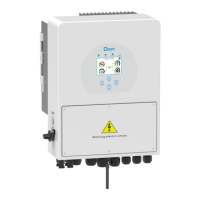
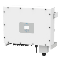
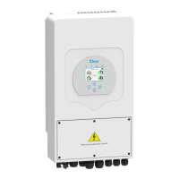
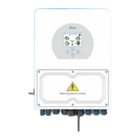
Detailed visual explanation of the inverter's components and ports.
Provides dimensions of the inverter and mounting bracket.
Lists the main features and capabilities of the hybrid inverter.
Guidelines for regular cleaning and checks to maintain inverter performance.
Lists all items included in the inverter package for installation.
Details site selection criteria and precautions for mounting the inverter.
Specifies the required DC over-current protector and cable size for battery connection.
Details AC breaker requirements and terminal block connections for grid and load.
Outlines requirements for connecting PV modules, including circuit breakers and cable size.
Explains how to connect the Current Transformer (CT) for monitoring power flow.
Explains the mandatory ground cable connection for electrical shock prevention.
Illustrates different wiring configurations for grid systems and distribution boxes.
Describes the procedure for turning the inverter on and off.
Explains the inverter's front panel indicators, function keys, and LCD display.
Details the information shown on the inverter's touchscreen main screen.
Provides a visual guide to navigating the inverter's LCD menu structure.
Explains how to view solar panel generation, voltage, current, and energy details.
Covers settings like time synchronization, beep, auto-dim, and factory reset.
Lists the sequential steps to follow after physical connection for grid commissioning.
Guides selection of grid codes and voltage levels based on regional standards.
Configures parameters like ramp rate, frequency, and voltage limits for grid connection.
Sets up over/under voltage and frequency protection points for grid stability.
Adjusts active and reactive power output based on grid voltage changes.
Configures reactive power and power factor settings related to active power.
Enables solar arc fault detection, primarily for US market applications.
Prevents generator overload by providing redundant power from the inverter.
Configures Demand Response Mode for AS4777 standard compliance.
Details solutions for GFDI relay failure, often related to grounding.
Explains causes and solutions for faults related to working mode or battery status changes.
Offers solutions for DC overcurrent faults, especially in off-grid mode with large loads.
Guides on resolving DC insulation impedance failures, focusing on PV grounding.
Lists troubleshooting steps for detecting no AC grid connection.
Guides on resolving AC line low voltage faults by checking voltage range and connections.
Addresses BMS communication faults, suggesting disabling BMS_Err_Stop or contacting support.
Provides steps for high heat sink temperature failures, including environment check and restart.
Details the pinout definition for RJ45 ports used for BMS communication.
Explains the function of the Meter_CON port for connecting energy meters.
Details the pinout definition for RJ45 ports used for the DRM (Demand Response) port.
| Model | SUN-3K-SG04LP1-24-AU |
|---|---|
| Type | Hybrid Inverter |
| Rated Power | 3kW |
| Rated AC Output Power | 3kW |
| Rated AC Voltage | 230V |
| Rated AC Frequency | 50/60Hz |
| THDi | <3% |
| Protection Degree | IP65 |
| Topology | Transformerless |
| Peak Efficiency | 97.6% |
| PV Input Voltage | 370 V |
| Max. AC Output Power | 3.3 kW |
| AC Voltage Range | 180V~280V |
| AC Grid Connection Type | Single-phase |
| Communication | RS485 |
| Cooling Method | Natural Cooling |