Do you have a question about the Deye SUN-40K-SG01HP3-EU-BM4 and is the answer not in the manual?
Guidelines for safely and correctly mounting the inverter unit.
Safety and environmental conditions to consider before installing the inverter.
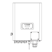
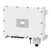
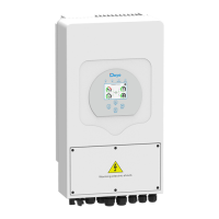
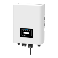
Detailed steps and diagrams for physically mounting the inverter unit.
Procedures and safety precautions for connecting the battery system.
Instructions for connecting the inverter to the grid and backup loads.
Procedures and safety guidelines for connecting photovoltaic modules.
Mandatory steps for establishing a proper earth ground connection for safety.
An example wiring diagram illustrating system connections in a distribution box.
An example wiring diagram for applications with neutral separated from PE.
Settings for battery mode, capacity, charging, and discharging parameters.
Configuration of different operational modes like Selling First or Zero Export.
Settings for grid connection, code selection, and protection parameters.
| Model | SUN-40K-SG01HP3-EU-BM4 |
|---|---|
| Rated Power | 40 kW |
| Max. DC Input Power | 60 kW |
| Nominal AC Output Power | 40 kW |
| Max. AC Output Power | 44 kW |
| Max. DC Input Voltage | 1100 V |
| MPPT Efficiency | 99.9% |
| Number of MPPT Trackers | 4 |
| Max. Input Current per MPPT | 26 A |
| Nominal AC Voltage | 400 V |
| AC Voltage Range | 310-480V |
| Nominal AC Grid Frequency | 50/60Hz |
| Frequency | 50/60Hz |
| THDi | <3% |
| DC Switch | Yes |
| Protection Degree | IP65 |
| Communication | RS485, Wi-Fi, Ethernet |
| Protection Level | IP65 |
| Input Voltage Range | 200 V - 1000 V |
| Operating Temperature Range | -25°C to 60°C |
| Operating Temperature | -25°C to +60°C |
| Type | Three Phase |
| Cooling Method | Smart Fan Cooling |