EasyManua.ls Logo

Deye SUN-5K-SG - User Manual

Deye SUN-5K-SG
17 pages
Print Icon
To Next Page IconTo Next Page
Loading...
5KW Storage Inverter Repairing Guide
SUN-5K-SG Repair Guide
When you see this sub-guide, it indicates that there is a problem
with the machine and needs to open the machine housing for
service. Before opening the Inverter Shell, the inverter's power
cables (including AC and DC) need to be disconnected altogether.
Wait at least 5 minutes before you can proceed.
1. Remove the screws counterclockwise
2. After removing the housing, carefully remove the shell, the housing liquid crystal
plate is connected to the inside of the machine. Take a photo of the interior and record
the location of each harness to prevent errors during installation and send us photos.
Question and Answer IconNeed help?

Do you have a question about the Deye SUN-5K-SG and is the answer not in the manual?

Summary

Inverter Service Preparation

Inverter Opening and Safety Precautions

Steps for safely opening the inverter housing and disconnecting power before service.

Troubleshooting DC Input and Insulation Errors

F-01 DC Input Polarity Reverse Fault

Diagnose reverse DC input polarity fault by checking PV panel connections.

F-02 DC Insulation Impedance Fault

Address DC insulation impedance fault by checking grounding and internal cables.

F-03 DC Leakage Current Fault

Troubleshoot DC leakage current fault by checking fuse and potential component damage.

Troubleshooting Ground, Memory, and Softstart Errors

F-04 Ground Fault GFDI

Identify ground fault by checking solar panel output terminals connection.

F-05 Read Memory Error

Address memory read errors by restarting and checking connections.

F-06 Write Memory Error

Resolve memory write errors by restarting and checking connections.

F-07 DC;DC Softstart Fault

Troubleshoot DC/DC softstart fault caused by low bus voltage.

F-08 GFDI Grounding Touch Failure

Note: GFDI grounding touch failure is not related to this machine.

Troubleshooting IGBT, Aux Power, and AC Contactor Errors

F-09 IGBT Damaged by Excessive Drop Voltage

Note: IGBT damage by voltage drop is not related to this machine.

F-10 Aux Power Board Failure

Diagnose Aux Power Board failure by checking MCU 12V power supply.

F-11 AC Main Contactor Errors

Troubleshoot AC main contactor errors by restarting the inverter.

F-12 AC Auxiliary Contactor Errors

Resolve AC auxiliary contactor errors by restarting the inverter.

F-13 Reserved

Indicates working mode change, phase loss, or relay issues.

Troubleshooting Firmware, Leakage, and Overcurrent Errors

F-14 DC Firmware Over Current

Note: DC firmware over current is not related to this machine.

F-15 AC Firmware Over Current

Note: AC firmware over current is not related to this machine.

F-16 GFCI(RCD) AC Leakage Current Fault

Note: GFCI AC leakage current fault is not related to this machine.

F-17 Three Phase Current, Over-current Fault

Note: Three phase over-current fault is not related to this machine.

F-18 Read Memory Error

Address AC current over max-limit by checking load power and firmware.

F-19 Read Memory Error

Note: This memory error is not related to this machine.

F-20 DC Over Current Fault Out of Hardware

Troubleshoot DC over current hardware fault by checking PV/battery connections.

F-21 DC Leakage Flow Fault

Note: DC leakage flow fault is not related to this machine.

Troubleshooting Tz, AC, and DC Busbar Errors

F-22 Tz_EmergSStop_Fault

Address Tz Emergency Stop Fault by checking GND connection.

F-23 AC Leakage Current is Transient Over Current

Diagnose AC leakage current transient fault by checking leakage sensor.

F-24 DC Insulation Impedance Failure

Resolve DC insulation impedance failure by checking PV panel and PE cable connections.

F-25 DC Feedback Fault

Note: DC feedback fault is not related to this machine.

F-26 The DC Busbar is Unbalanced

Note: DC busbar imbalance is not related to this machine.

F-27 DC End Insulation Error

Note: DC end insulation error is not related to this machine.

F-28 Inverter 1 DC High Fault

Note: Inverter 1 DC high fault is not related to this machine.

F-29 Parallel CANBus Fault

Troubleshoot parallel CANBus fault by checking settings and connections.

F-30 AC Main Contactor Failure

Note: AC main contactor failure is not related to this machine.

F-31 DC Boost Soft Start

Note: DC boost soft start is not related to this machine.

Troubleshooting Inverter High Fault and Grid Errors

F-32 Inverter 2 DC High Fault

Note: Inverter 2 DC high fault is not related to this machine.

F-33 AC Over Current

Note: AC over current is not related to this machine.

F-34 AC Current Over Load

Note: AC current over load is not related to this machine.

F-35 No AC Grid

Address 'No AC Grid' fault by confirming grid connection and status.

F-36 AC Grid Phase Error

Note: AC grid phase error is not related to this machine.

F-37 AC Three-phase Voltage Unbalance Failure

Note: AC voltage unbalance failure is not related to this machine.

F-38 AC Three-phase Current Unbalance Failure

Note: AC current unbalance failure is not related to this machine.

F-39 AC Over Current (One Cycle)

Note: AC over current (one cycle) is not related to this machine.

F-40 DC Over Current

Note: DC over current is not related to this machine.

Troubleshooting Parallel, AC Voltage, and Frequency Errors

F-41 Parallel System Stop

Address parallel system stop faults due to other inverter issues.

F-42 AC Line Low Voltage

Troubleshoot AC line low voltage by checking AC voltage and cable connections.

F-43 AC Line V,W Over Voltage

Note: AC line V,W over voltage is not related to this machine.

F-44 AC Line V,W Low Voltage

Note: AC line V,W low voltage is not related to this machine.

F-45 AC Line U,V Over Voltage

Note: AC line U,V over voltage is not related to this machine.

F-46;49 Backup Battery Fault

Address backup battery faults by checking capacity and connections.

F-47 AC Over Frequency

Troubleshoot AC over frequency by checking frequency and cable connections.

F-48 AC Lower Frequency

Note: AC lower frequency is not related to this machine.

Troubleshooting Backup Battery and DC Busbar Errors

F-49;46 Backup Battery Fault

Address backup battery faults by checking capacity and connections.

F-50 V Phase Grid Current DC Component Over Current

Note: V phase grid current fault is not related to this machine.

F-51 W Phase Grid Current DC Component Over Current

Note: W phase grid current fault is not related to this machine.

F-52 AC Inductor B, Phase Current DC Current High

Note: AC inductor B current fault is not related to this machine.

F-53 Read Memory Error

Note: This memory error is not related to this machine.

F-54 AC Inductor C, Phase Current DC Current High

Note: AC inductor C current fault is not related to this machine.

F-55 DC Busbar Voltage is Too High

Address high DC busbar voltage by checking PV or battery voltage.

F-56 DC Busbar Voltage is Too Low

Resolve low DC busbar voltage by checking battery voltage.

Troubleshooting AC Irrigation, Battery, and Reactor Errors

F-57 AC Reverse Irrigation

Note: AC reverse irrigation is not related to this machine.

F-58 Battery Over Current

Check battery discharge current is within allowed range.

F-59 AC Grid V Over Current

Note: AC grid V over current is not related to this machine.

F-60 AC Grid W Over Current

Note: AC grid W over current is not related to this machine.

F-61 Reactor A Phase Over Current

Note: Reactor A phase over current is not related to this machine.

F-62 Reactor B Phase Over Current

Note: Reactor B phase over current is not related to this machine.

F-63 ARC Fault

Address ARC fault by checking PV module cable connection.

F-64 Heat Sink High Temperature Failure

Resolve heat sink high temperature by checking environment and restarting.

IGBT and Diode Testing Guide

IGBT Measurement Procedure

Steps for measuring IGBT and diode voltage drop using a multimeter.

IGBT Testing with Multimeter

Instructions for setting multimeter and measuring IGBT S-level and D-level.

Boost Diode Testing

Procedure for measuring the voltage drop of the boost diode.

IGBT Component Identification and Replacement

IGBT Drive Component Identification

Identify and replace IGBT drive components and resistors.

IGBT Replacement Guidelines

Ensure all damaged IGBTs are replaced and pay attention to component direction.

Post-Replacement Checks and Inductor Testing

Checking Marked Components for IGBT Replacement

Replace marked components corresponding to damaged IGBTs.

Inductor Harness and Shell Contact Check

Verify inductor harness integrity and check for direct contact with the shell.

Motherboard Assembly and Harness Connection

Installing the Control Panel

Procedure for installing the control panel and plugging in harnesses.

Connecting Inductive Wires

Insert inductive wire terminals into motherboard positions, following line labels.

Internal Component Assembly and Wiring

Connecting 60 P Gray Line

Connect the 60P gray line to the motherboard and control board.

Securing Capacitor Plate and Cables

Replace capacitor plate and secure cables with screws.

Final Assembly and Testing

Connecting Button Switch and AC Wires

Pass button switch cable and connect AC wire, yellow green line.

Installing Top Cover and Testing

Install the top cover, test the machine, and seek service if problems persist.

Overview

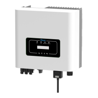
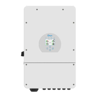
The Deye 5KW Storage Inverter is a sophisticated device designed for managing and converting solar energy, offering robust functionality for both residential and commercial applications. This guide provides comprehensive instructions for its repair and maintenance, highlighting its modular design and the importance of precise handling during service.

Function Description

The Deye 5KW Storage Inverter primarily functions as a central unit for solar power systems, converting direct current (DC) generated by solar panels into alternating current (AC) suitable for household use or feeding into the grid. It also incorporates storage capabilities, allowing excess energy to be stored in batteries for later use, enhancing energy independence and reliability. The inverter is equipped with various protection mechanisms to ensure safe and efficient operation, including safeguards against DC input polarity reversal, insulation impedance faults, DC leakage current, ground faults, and AC overcurrents. It can operate in parallel mode, allowing multiple inverters to work together for increased power output and system redundancy. The device's control system monitors critical parameters such as bus voltage, AC line voltage, and frequency, adjusting its operation to maintain optimal performance and protect against anomalies. Its ability to manage both PV input and battery storage makes it a versatile solution for hybrid solar energy systems.

Usage Features

The inverter is designed for user-friendly operation, though its internal components require careful handling during maintenance. Key usage features include:

  • Error Code System: The inverter utilizes a detailed error code system (F-01 to F-64) to diagnose and indicate specific operational issues. These codes cover a wide range of faults, from DC input problems and memory errors to AC output issues and internal component failures. This system allows for quick identification of problems, facilitating efficient troubleshooting.
  • Parallel Operation: For systems requiring higher power output or enhanced reliability, the inverter supports parallel operation. This feature allows multiple Deye inverters to work in conjunction, sharing the load and providing a scalable energy solution.
  • Grid Interaction: The inverter is designed to interact seamlessly with the utility grid. It can feed excess solar energy into the grid, reducing electricity bills, and can also draw power from the grid when solar generation is insufficient or batteries are depleted.
  • Battery Management: A crucial feature is its integrated battery management, which allows for the storage of solar energy. This enables users to utilize stored energy during peak demand hours or at night, reducing reliance on the grid and improving energy self-consumption. The system monitors battery voltage and capacity, ensuring optimal charging and discharging cycles.
  • Safety Mechanisms: The inverter incorporates multiple safety features, such as protection against reverse polarity, ground faults (GFDI), and AC/DC overcurrents. These mechanisms are critical for protecting the device, the connected electrical system, and users from potential hazards.
  • Monitoring and Control: While not explicitly detailed in the provided text, the presence of a liquid crystal plate and the need for internal harness connections suggest that the inverter offers local monitoring and control capabilities, allowing users to view operational status and potentially adjust settings.

Maintenance Features

Maintenance of the Deye 5KW Storage Inverter is designed to be systematic, with a strong emphasis on safety and precision. The repair guide outlines several key maintenance features:

  • Modular Design: The inverter appears to have a modular internal structure, with components like the control board, power board, and various sensors being accessible for inspection and replacement. This modularity simplifies troubleshooting and component-level repairs.
  • Pre-Service Safety Protocols: Before any internal maintenance, strict safety protocols must be followed. This includes disconnecting all power cables (AC and DC) and waiting at least 5 minutes to allow internal capacitors to discharge, preventing electric shock.
  • Visual Inspection and Documentation: Technicians are instructed to take photos of the inverter's interior and record the location of each harness before disassembly. This practice is crucial for preventing errors during reassembly and ensuring all connections are correctly restored.
  • Component-Level Troubleshooting: The guide provides specific instructions for troubleshooting various components. For instance, in cases of DC leakage current, checking the battery fuse with a multimeter is recommended. For memory errors (EEPROM), restarting the inverter and, if the error persists, replacing the control board are suggested steps.
  • IGBT and Diode Testing: A significant portion of the maintenance guide focuses on testing IGBTs (Insulated Gate Bipolar Transistors) and diodes, which are critical power electronic components. The process involves using a multimeter in diode gear to measure voltage drops across these components. Specific voltage ranges (e.g., 0.405V for S-level, 0.450V for G-level in IGBTs, and 0.33V for Boost diodes) are provided as benchmarks. Deviations, especially values close to 0, indicate damage.
  • Associated Component Replacement: If an IGBT is found to be damaged, the corresponding drive components (e.g., optocouplers, resistors) also need to be measured or replaced. The guide emphasizes paying attention to the direction of these components and ensuring all damaged parts are replaced.
  • Post-Replacement Checks: After replacing components, a thorough check of internal inductors and other harnesses for breakage or direct contact with the shell is mandatory. Measuring the resistance between the inductor harness and the housing (which should be infinite) is a critical step to ensure proper insulation and prevent future faults.
  • Reassembly Instructions: The guide provides detailed steps for reassembling the inverter, including installing the control panel, plugging in harnesses, securing inductive wires, and connecting various cables (e.g., 60P gray line, battery discharge current cables, AC wire, yellow-green line). Attention to wire labels and PCB silk screen consistency is repeatedly stressed to ensure correct connections.
  • Final Testing: After reassembly, the inverter must be tested to confirm proper functionality. If problems persist, seeking assistance from Deye Service is recommended.
  • Environmental Considerations: For issues like heat sink high temperature failure, checking the work environment temperature and allowing the inverter to cool down by turning it off for 10 minutes are suggested, highlighting the importance of environmental factors in the inverter's operation.

In summary, the Deye 5KW Storage Inverter is a robust and repairable device, designed with an emphasis on diagnostic clarity and systematic maintenance procedures. Its comprehensive error code system, modular construction, and detailed repair instructions empower technicians to efficiently troubleshoot and restore the inverter to optimal working condition, ensuring reliable solar energy management.

Deye SUN-5K-SG Specifications

General IconGeneral
TypeHybrid Inverter
Rated Power5kW
Max. DC Input Power6.5kW
Max. DC Input Voltage500V
Number of MPPT Trackers2
Nominal AC Output Power5kW
Max. AC Output Power5.5kW
AC Voltage Range180-280V
THDi<3%
AC Grid Frequency Range50/60Hz
Battery Voltage Range40-60V
Max. Charging Current100A
Max. Discharging Current100A
Protection DegreeIP65
TopologyTransformerless
Nominal AC Voltage230 V
Power Factor0.8 leading to 0.8 lagging
CommunicationRS485
Cooling MethodNatural Cooling
Operating Temperature Range-40~60°C

Related product manuals