Do you have a question about the Deye SUN-5K-SG01LP1-EU and is the answer not in the manual?
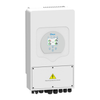
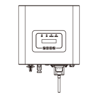
Detailed description of the inverter's physical components and their functions.
Specifications for the physical dimensions of the inverter and its mounting bracket.
Key functionalities and capabilities of the hybrid inverter system.
Illustrative diagram showing the inverter's integration within a typical solar power system.
List of all items included in the inverter package for installation.
Guidelines and precautions for securely mounting the inverter unit.
Step-by-step instructions for safely connecting the battery to the inverter.
Procedures for connecting the inverter to the AC grid and backup load.
Instructions for connecting the photovoltaic (PV) modules to the inverter.
Diagrams illustrating typical wiring configurations for grid-tied systems.
Schematics for connecting multiple inverters in parallel for increased capacity.
Procedure for turning the hybrid inverter unit on and off.
Overview of the inverter's front panel controls, indicators, and LCD display.
Description of the primary inverter display screen and its information elements.
Visual guide illustrating navigation paths and interactions within the inverter's LCD menu.
Details and interpretation of the solar panel power generation data displayed.
Explanation of graphical representations for daily, monthly, and yearly power generation and consumption.
Access point for configuring various system parameters and settings.
Menu for configuring fundamental inverter settings like time sync and factory reset.
Options for configuring battery parameters, capacity, and charging modes.
Settings to define operational modes like selling, zero export, and energy priority.
Parameters for configuring the inverter's interaction with the AC power grid.
Configuration options for utilizing the generator input port for power supply.
Settings for advanced features such as arc fault detection and peak shaving.
Display of inverter identification, version information, and alarm codes.
Description of the basic operational mode without additional components.
Configuration for operating the inverter with a wind turbine system.
Setup for integrating a generator into the system for backup power.
Operational mode utilizing a smart load for optimized power management.
Configuration for AC-coupled systems, often involving existing grid-tied inverters.
List of error codes, their descriptions, and recommended troubleshooting solutions.
Technical specifications related to battery type, voltage, and current.
Technical specifications for PV module input, voltage, and current.
Technical specifications for the inverter's AC output power and current.
List of regulatory standards and certifications the inverter complies with.
List of compatible battery brands and their recommended setup parameters.
Pinout definitions for the RJ45 ports used for Battery Management System communication.
Physical dimensions and specifications for the split core current transformer (CT).
| Model | SUN-5K-SG01LP1-EU |
|---|---|
| Type | Hybrid Inverter |
| Rated Power | 5000 W |
| Max. DC Input Power | 6500 W |
| Start-up Voltage | 150 V |
| Number of MPPT Trackers | 2 |
| Number of Strings per MPPT Tracker | 1 |
| Max. Input Current per MPPT Tracker | 13A |
| Rated AC Output Power | 5000 W |
| Max. AC Output Power | 5500 VA |
| Rated AC Voltage | 230 V |
| AC Voltage Range | 180-280V |
| Rated AC Frequency | 50/60Hz |
| THDi | <3% |
| DC Injection Current | <0.5% In |
| Switching Time | 10ms |
| Max. Charging Power | 5000 W |
| Max. Discharging Power | 5000 W |
| Battery Voltage Range | 40-60V |
| Max. Charging Current | 100 A |
| Max. Discharging Current | 100 A |
| Max Efficiency | 97.6% |
| Noise Level | <30 dB |
| Protection Degree | IP65 |
| MPPT Voltage Range | 125 V - 550 V |
| Power Factor | 0.8 leading to 0.8 lagging |
| Communication with BMS | CAN |
| Operating Temperature | -25°C to +60°C |
| Humidity | 0~95% |