Do you have a question about the Deye SUN 5K-SG01LP1-US and is the answer not in the manual?
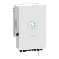
Provides a detailed overview of the inverter's features and components.
Displays the physical dimensions and measurements of the inverter unit.
Lists and describes the key functionalities and capabilities of the inverter.
Illustrates the fundamental setup and connection of the inverter within a system.
Enumerate all components included in the inverter package for installation.
Provides guidelines and precautions for securely mounting the inverter unit.
Details the procedure for connecting the battery bank to the inverter.
Explains the purpose and connection of various function ports on the inverter.
Guides the connection of the temperature sensor for lead-acid battery monitoring.
Outlines how to connect the inverter to the grid and backup load.
Describes the process for connecting photovoltaic (PV) modules to the inverter.
Criteria and parameters for choosing suitable PV modules for the inverter.
Step-by-step instructions for wiring PV modules to the inverter input.
Details the connection procedure for current transformers (CTs).
Explains how to connect energy meters to the inverter.
Emphasizes the mandatory grounding procedure for safety.
Guides the setup and connection of the Wi-Fi module for monitoring.
Illustrates various wiring configurations for the inverter system.
Shows how to integrate a diesel generator into the system.
Diagram for single-phase parallel connection of inverters.
Diagram for split-phase parallel connection of inverters.
Wiring diagram for three-phase parallel connection.
Diagram for 120/208V three-phase parallel connection.
Wiring for 120/208V three-phase parallel connection.
Instructions for turning the inverter on and off.
Overview of the inverter's front panel controls and display.
Description of the primary display screen showing system status and data.
Visual representation of solar power generation over time.
Displays power curves for solar, load, and grid.
Access point for configuring various system parameters.
Configuration options for battery settings and management.
Options for selecting and setting the inverter's operational modes.
Settings related to grid connection parameters and modes.
Configures the generator input port for various operational scenarios.
Access to advanced features and settings for specialized configurations.
Displays information about the inverter, including ID and firmware versions.
Describes the basic operating mode of the inverter without external devices.
Illustrates system configuration when a generator is connected.
Shows system setup with smart load functionality enabled.
Diagrams for AC coupling configurations with other inverters.
Details the pin assignments for RJ45 ports used for BMS communication.
Provides dimensional specifications for the split core current transformer.
| Model | SUN 5K-SG01LP1-US |
|---|---|
| Type | Hybrid Inverter |
| Rated Output Power | 5000 W |
| Max. DC Input Power | 6500 W |
| Max. AC Output Power | 5000 W |
| Nominal AC Voltage | 120/240V |
| AC Output Frequency | 60 Hz |
| Max. Charging/Discharging Current | 100 A |
| Battery Voltage Range | 40-60V |
| Max. DC Input Voltage | 500V |
| Start-up Voltage | 150 V |
| Number of MPPT Trackers | 2 |
| Max. Input Current per MPPT | 13 A |
| Communication | RS485, Wi-Fi |
| Warranty | 5 years |
| Peak Efficiency | 97.6% |
| Protection Class | IP65 |
| Operating Temperature | -25°C to 60°C |