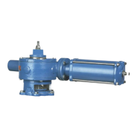
The DeZURIK G-Series Actuator is a manual operator designed for use with PEF 100% Port Eccentric Plug Valves. This instruction manual, D10456, provides detailed information for installation, operation, and maintenance of these actuators.
Function Description
The G-Series actuator manually operates PEF 100% Port Eccentric Plug Valves. It features external adjustable stops that limit the actuator's stroke for both open and closed valve positions, ensuring optimal shutoff and flow. Rotating the operator (handwheel, chainwheel, or 2-inch nut) clockwise closes the valve, while counterclockwise rotation opens it. The actuator can be mounted in 90-degree increments around the valve shaft, offering flexibility in installation.
Important Technical Specifications
The G-Series actuator is available in two sizes: Size 6 and Size 12.
- Size 6: Requires 13 revolutions of the operator to actuate the valve from full open to full closed (or vice-versa).
- Size 12: Requires 19 revolutions of the operator to actuate the valve from full open to full closed (or vice-versa).
- Fasteners: The actuator is assembled using metric fasteners.
- Lubrication: Factory-lubricated and requires no routine maintenance lubrication under normal operating conditions.
- Actuator Input Torque (ft-lbs):
- Valve Size 3 & 4 (G6): Direct Pressure Drop (psi) 4; Reverse Pressure Drop (psi) ranges from 4 (25 psi) to 5 (175 psi).
- Valve Size 5 (G6): Direct Pressure Drop (psi) 8; Reverse Pressure Drop (psi) ranges from 8 (25 psi) to 11 (75-175 psi).
- Valve Size 6 (G6): Direct Pressure Drop (psi) 8; Reverse Pressure Drop (psi) ranges from 8 (25 psi) to 11 (75-175 psi).
- Valve Size 8 (G6): Direct Pressure Drop (psi) 15; Reverse Pressure Drop (psi) ranges from 15 (25 psi) to 21 (125-175 psi).
- Valve Size 10 (G6): Direct Pressure Drop (psi) 22; Reverse Pressure Drop (psi) ranges from 22 (25 psi) to 36 (125 psi). N/A for 150-175 psi.
- Valve Size 10 (G12): Direct Pressure Drop (psi) 11; Reverse Pressure Drop (psi) ranges from 11 (25 psi) to 18 (50-175 psi).
- Valve Size 12 (G6): Direct Pressure Drop (psi) 29; Reverse Pressure Drop (psi) ranges from 29 (25-100 psi). N/A for 125-175 psi.
- Valve Size 12 (G12): Direct Pressure Drop (psi) 15; Reverse Pressure Drop (psi) ranges from 15 (25-175 psi).
- Valve Size 14 (G12): Direct Pressure Drop (psi) 18; Reverse Pressure Drop (psi) ranges from 18 (25 psi) to 34 (100-150 psi). N/A for 175 psi.
- Valve Size 16 (G12): Direct Pressure Drop (psi) 22; Reverse Pressure Drop (psi) ranges from 22 (25 psi) to 45 (100-150 psi). N/A for 175 psi.
- Valve Size 18 (G12): Direct Pressure Drop (psi) 26; Reverse Pressure Drop (psi) ranges from 26 (25 psi) to 55 (100-125 psi). N/A for 150-175 psi.
- Valve Size 20 (G12): Direct Pressure Drop (psi) 29; Reverse Pressure Drop (psi) ranges from 29 (25 psi) to 55 (100 psi). N/A for 125-175 psi.
- Pressure Direction: Valves can be mounted with Direct Pressure (higher pressure at the end opposite the seat) or Reverse Pressure (higher pressure at the seat end).
Usage Features
- Stop Adjustments: The open and closed position stops are preset if the actuator is factory-mounted. If not, or if the actuator has been removed, adjustments are required.
- Closed Position Stop Adjustment: Requires discontinuing flow, relieving pipeline pressure, closing the valve, loosening the nut on the closed position screw, backing out the screw, turning the operator until the specified Actuator Input Torque is reached, then turning the closed position screw clockwise until resistance is felt, and finally tightening the nut.
- Open Position Stop Adjustment: Similar to closed position, but involves visually determining the open position (removing pointer/cover for Above Ground/Buried Service respectively), loosening the nut on the open position screw, turning the operator until the drive key/plug alignment is parallel to the valve flanges, turning the open position screw clockwise until resistance is felt, and then tightening the nut. For Above Ground Service, the pointer is replaced, pointing to "OPEN." For Buried Service, old sealant is removed, new silicone sealant (DOW RTV-732 or similar) is applied, and the cover is fastened.
- Actuator Mounting Position: The actuator can be rotated and mounted in 90-degree increments around the valve shaft. This involves removing the actuator, rotating it, and then reinstalling it.
- Operator Component Identification: The manual provides detailed diagrams for identifying components of actuators with wrenching squares, handwheels, and chainwheels, including pins, handwheels, chainwheels, chain guides, bearings, collars, set screws, chains, closing links, wrenching squares, open tags, drive screws, adaptors, screws, lockwashers, and bearings.
- Replacing Handwheel or Wrenching Square with Chainwheel:
- G_-6A and G_-12A (3" - 12" valves): Involves supporting the actuator shaft, driving out the pin, removing the handwheel/wrenching square, sliding the collar onto the shaft, assembling the bearing, chain guide, and chainwheel, aligning pin holes, driving in connecting and retaining pins, sliding the collar up to the bearing, tightening the set screw, feeding the chain, and connecting chain ends. A retaining pin is crucial to prevent disengagement and injury.
- G_-12A (14" - 20" valves): Similar steps, but also includes removing plastic plugs, sliding an adaptor onto the shaft, tightening it with screws and lockwashers, and then proceeding with collar, bearing, chain guide, and chainwheel assembly.
- Replacing Chainwheel with Handwheel or Wrenching Square: Involves supporting the chainwheel hub, driving out pins, removing the chainwheel and chain guide assembly, loosening the set screw, sliding the collar off, and for GS-12A on 14"-20" valves, removing the adaptor. Finally, sliding the handwheel/wrenching square onto the shaft, aligning the pin hole, and driving in the pin.
Maintenance Features
- Inspection: Upon arrival, the unit should be carefully inspected for damage, and a claim filed with the carrier if damage is apparent.
- Parts Ordering: Recommended spare parts are listed on the assembly drawing. When ordering, the 7-digit part number, 4-digit revision number (e.g., 9999999R000) from the data plate, part name, assembly drawing number, balloon number, and quantity are required.
- Tools Required: Full set of combination or ratchet wrenches, Allen wrenches, flat-tipped screwdrivers, a 1/4” pin punch, and a dead blow hammer.
- Actuator Disassembly and Assembly: Under normal operating conditions, routine maintenance is not required. If excessive wear or damage occurs, replacement is recommended over repair. However, procedures for replacing leaking seals and o-rings are provided.
- Disassembly: Involves discontinuing flow, relieving pipeline pressure, closing the valve or rotating the plug to the lowest position, removing the actuator from the valve, noting the position of the pointer/removing covers for Above Ground/Buried Service, removing screws and cover, removing o-rings, noting gear position, sliding out the gear, removing pipe plugs, rotating the drive shaft to align pins, driving out pins, sliding out the drive shaft, removing seals and o-rings, and removing old gasket sealant.
- Assembly: Involves installing new seals, sliding the drive shaft through bearings and worm, rotating the drive shaft to align pin holes, driving in pins, applying thread sealant to pipe plugs, applying grease to new o-rings, greasing bearings, sliding the gear into position, applying liberal amounts of Lithium-based grease (Shell Alvania EP2 or Mobilux EP2) to gear, bearings, and worm (or packing the housing full for Buried Service), applying grease to new o-rings in the cover, applying silicone sealant to mating surfaces, greasing the bearing in the cover, sliding the cover onto the gear, fastening with screws, inserting the drive key, fastening the pointer for Above Ground Service (or applying sealant and fastening cover for Buried Service), and finally installing the actuator on the valve.
- Troubleshooting: A table is provided to address common issues:
- Actuator closes/opens to wrong position: Possible causes include incorrectly set closed/open position stops or incorrectly installed pointer. Corrective actions involve adjusting the stops or rotating the pointer.
- Actuator will not fully operate valve: Possible causes include pipeline obstruction or misalignment of the adaptor. Corrective actions involve removing obstruction or checking/adjusting valve-adaptor actuator alignment.
- High operating torque: Possible causes include misalignment of ENK extension or bent actuator input shaft. Corrective actions involve checking/adjusting valve-extension-actuator alignment or replacing the actuator.
- Safety Messages: Emphasizes constant alertness to potential emission of pipeline material, wearing suitable protection, handling removed valves with protection, and shutting down flow and relieving pipeline pressure before making stop adjustments or removing the actuator to prevent personal injury and equipment damage. Specific warnings are given regarding the risk of the valve slamming shut if the actuator is removed while flow is present, and the plug swinging to a lower position due to gravity in certain mounting orientations. A warning is also included about the potential for the chainwheel connecting pin to shear, causing disengagement and injury, stressing the importance of a retaining pin.
- DeZURIK Service: DeZURIK service personnel are available for installation, maintenance, and repair, and offer customized training programs and consultation services.