Do you have a question about the Dhollandia DH-RPM 25 and is the answer not in the manual?
| Brand | Dhollandia |
|---|---|
| Model | DH-RPM 25 |
| Category | Farm Equipment |
| Language | English |
Explains general warning signs, danger, caution, notice, and safety instructions used in the manual.
Emphasizes risks of serious injury or death from improper use and failure to follow instructions.
Highlights severe risks of injury or death due to improper installation.
Advises confirming the most up-to-date manual version before operation.
Outlines manufacturer's disclaimer for modifications, improper use, and installation.
Warns that improper use risks serious bodily injury or death to operators and bystanders.
Stresses reviewing the most up-to-date manual for safe operation.
Highlights dangers to installers from ignorance or neglect during installation.
Advises disconnecting power and following specific cautions for electrical work.
Defines key terms related to liftgate dimensions and installation parameters.
Provides initial steps and crucial checks before starting the liftgate installation process.
Presents diagrams and measurements for two different bed height ranges.
Advises contacting the DHOLLANDIA distributor for any doubts on installation parameters.
Provides guidance on chassis cut dimensions for different bed heights.
Notes regarding recommended dimensions, deviations, and anti-corrosive coating.
Illustrates rear sill cut requirements for different bed heights and mentions anti-corrosive coating.
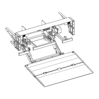
Details steps for aligning, drilling, and bolting the bed extension to the rear sill.
Warns about the heavy weight of the bed extension and the need for lifting aids.
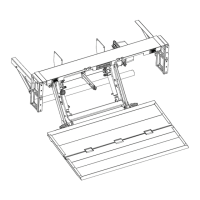
Shows how to weld the bed extension and specifies areas to avoid welding.
Warns about the heavy weight of the lift frame and the need for lifting aids.
Explains how to adjust the platform to ensure it is level.
Details steps for attaching the lift frame using hoists or forklifts.
Shows how to fit and align mount plates for standard chassis widths.
Illustrates mount plate configuration for wider or cutaway chassis.
Describes using alignment tubes and counterweights for positioning the lift frame.
Details how to mount the liftgate using a forklift with appropriate precautions.
Explains how to hoist, jack, and secure the lift frame for proper alignment.
Details bolting mount plates to the chassis, including torque and quantity.
Guides on bolt placement and adhering to vehicle manufacturer's chassis instructions.
Provides minimum weld counts and lengths for securing mount plates.
Stresses the importance of subframe/long rail connection strength if not bolted.
Advises contacting distributor for doubts and warns of risks from negligence.
Details mounting the toggle switch and routing its electrical cable to the pump unit.
Shows the wiring diagram for the toggle switch (primary control).
Explains the cabin switch function and wiring requirements, minimum 16 AWG.
Details mounting the 2-button remote control and routing its cable.
Presents the wiring diagram for the 2-button remote control.
Covers connecting battery cables, fuse, and ground cable to motor terminals.
Illustrates routing and connecting positive and negative battery cables to the motor.
Recommends dual cables, protective conduits, dielectric grease, and proper routing.
Ensures correct installation, torque, and electrical connections before powering up.
Guides on initial lift/lower operations and checking for leaks and air in circuits.
Details the process for bleeding air from the hydraulic circuits.
Explains how to adjust the platform opener for proper leaning and unfolding.
Warns that torsion springs are dangerous and adjustment requires trained personnel.
Guides on ensuring the platform is level and adjusting its pitch for optimal loading.
Details mounting side steps to the bed extension, considering step size and angle.
Describes welding support channels and applying anti-corrosive coating.
Warns about impacts of increased ground clearance and suggests flexible steps.
Provides instructions for mounting optional 102" body widening blocks.
Details mounting an optional bumper light cluster kit for rear lamps.
Guides on lubricating articulation points with acid-free grease after installation and in service.
Illustrates specific grease points (GP1-GP12) on the liftgate assembly.
Details checks for platform alignment, folding, and visibility in traffic.
Advises marking a safe operator zone to prevent crushing hazards.
Covers adjusting hydraulic blow-off pressure during weight testing and sealing the relief valve.
Warns that operating a liftgate without a successful PDI can cause damage or injury.
Shows placement of various safety and information decals on the liftgate and vehicle.
Details specific decals related to safety instructions, capacity, and wiring.
Instructs on using the "Out of Service" sign when maintenance or repair is needed.
Explains various warning, mandatory action, and prohibition signs used in the manual.
Details signs for electric/hydraulic functions like open, lower, lift, close, slide, and stabilizing legs.
Provides a table of metric and imperial torque values for various bolt sizes and stress types.
Lists recommended cable sizes and minimum battery/generator requirements for different systems.
Lists recommended hydraulic oil types and warns against using unsuitable fluids.
Details risks for operators on the platform and how to maintain safe positions.
Concludes the manual, emphasizing maintenance and authorized service.
Explains where to find basic wiring diagrams and how to obtain copies.
Refers to subsequent pages for a preventative maintenance and care checklist.