EasyManua.ls Logo

Dhollandia DH-RPH 33 User Manual

Dhollandia DH-RPH 33
56 pages
To Next Page IconTo Next Page
Page #1 background imageLoading...
Page #1 background image
Order ref : xxx Doc: FIT_US installation manual RPH_US EN_2022 Rev: 0 Date: APRIL 20, 2022
DH-RPH 33
INSTALLATION MANUAL
Read the manual in its entirety before operating the liftgate
Keep this manual in the vehicle cab, as reference for the driver and liftgate operator
Manufacturer:
DHOLLANDIA US, L.L.C.
E-mail : us.info@dhollandia.com
270 Southridge Parkway
Bessemer City North Carolina, 28016
website : www.dhollandia.com
Question and Answer IconNeed help?

Do you have a question about the Dhollandia DH-RPH 33 and is the answer not in the manual?

Dhollandia DH-RPH 33 Specifications

General IconGeneral
BrandDhollandia
ModelDH-RPH 33
CategoryFarm Equipment
LanguageEnglish

Summary

1 UNDERSTANDING SAFETY AND WARNING SIGNS

2 INTRODUCTION, CONTACT INFO AND DISCLAIMERS

3 SAFETY PRECAUTIONS FOR OPERATION

4 SAFETY PRECAUTIONS FOR INSTALLATION

5 LIFTGATE TERMINOLOGY

5.1 DH-RPH LIFTGATE TERMINOLOGY

Refer to the OPERATION MANUAL for an overview of the most important terminology used in DHOLLANDIA manuals.

5.2 INSTALLATION PARAMETERS TERMINOLOGY

Defines various parameters like LARM, VFH MAX, CTH MAX, MFC, MFT, MPG, PD.

5.3 GETTING STARTED

Provides initial steps and considerations before commencing liftgate installation.

6 INSTALLATION DIMENSIONS AND GUIDELINES

6.1 INSTALLATION DIMENSIONS

Illustrates critical dimensions for mounting the liftgate based on bed heights.

6.2 INSTALLATION RESOURCES

Guidance on contacting distributors for installation parameter doubts.

7 BED EXTENSION AND CHASSIS CUT

7.1 REAR SILL CUT

Provides specific dimensions and instructions for cutting the rear sill of the vehicle.

8 MOUNTING OF THE BED EXTENSION

9 MOUNTING OF THE LIFT FRAME (PREMOUNTED PLATFORM)

10 FIXATION OF THE MOUNT PLATES

10.1 FIXATION OF THE MOUNT PLATES OAM010

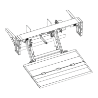
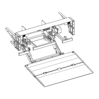
Details on how to attach the mount plates to the lift frame and chassis.

10.2 GENERAL REMARKS

Additional considerations for mounting plate installation and chassis connection.

11 INSTALLATION OF ELECTRICAL CONTROLS

11.1 INSTALLATION OF THE CONTROL SWITCH (OAE015.PR – E0832.B)

Guide for mounting the primary control toggle switch.

11.2 INSTALLATION OF THE CABIN SWITCH (OAE510.15 – E0393.S.15)

Instructions for installing the cabin-mounted control switch.

11.3 INSTALLATION OF EXTRA CONTROLS – 2 BUTTON REMOTE CONTROL (OAE001 – E0787.2.H)

Steps for mounting and wiring the 2-button remote control.

12 ELECTRICAL INSTALLATION

12.1 INSTALLATION OF THE (+) BATTERY CABLE AND (-) GROUND CABLE

Procedure for connecting the main power cables to the liftgate.

13 PUTTING THE LIFTGATE INTO SERVICE

14 PLATFORM ORIENTATION

15 MOUNTING OF THE SIDE STEPS

15.1 MOUNTING THE SIDES STEPS

Instructions for attaching the side steps to the bed extension.

15.2 MOUNTING OF THE OPTIONAL WIDENING BLOCKS (OAM053)

Procedure for installing optional widening blocks for the bed extension.

15.3 MOUNTING OF THE OPTIONAL BUMPER LIGHT CLUSTER KIT (OAM060)

Steps for installing the optional bumper light cluster kit.

16 LUBRICATION INSTRUCTIONS

17 QUALITY CONTROL AND PDI

18 DECALS

19 APPENDIX

19.1 MEANING OF THE SAFETY AND WARNING SIGNS

Explanation of various safety signs and their corresponding actions.

19.2 PRESCRIBED TORQUE VALUES FOR BOLTS AND NUTS

Table of recommended torque specifications for various bolt sizes.

19.3 ELECTRIC AND HYDRAULIC REQUIREMENTS

Specifications for electrical and hydraulic system components and sizing.

19.4 SAFE OPERATOR POSITION ON THE PLATFORM

Guidelines for safe positioning and movement of the operator on the platform.

19.5 END NOTE

Final remarks, warranty, and additional information sources.

19.6 BASIC WIRING DIAGRAMS

Information on accessing and obtaining wiring diagrams.

19.7 CHECKLIST FOR PREVENTATIVE MAINTENANCE AND REPAIR

Reference to detailed maintenance and repair checklists.

Related product manuals