DETAIL 1
DETAIL 2
DETAIL 3
DETAIL 4
DETAIL 5
7 /15
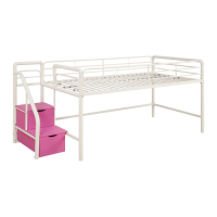
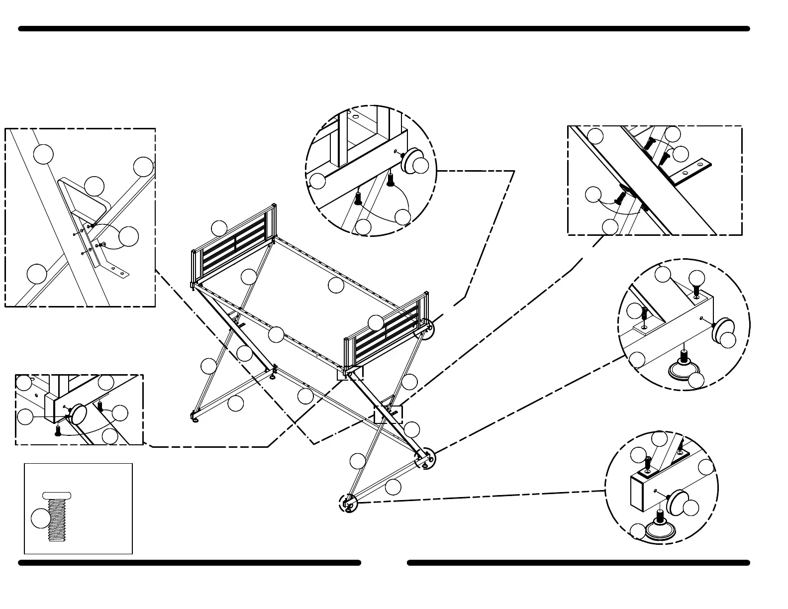
As shown in detail (1 & 2), attach the Right Base (D) to the King Support (A) & Bottom Brace (B). As shown in detail (3 & 6)
attach the Upper Brace (C) and Safety Bracket (V) to the King Support (A).
Attach the Right Guard Rail (E) to the Upper Brace (C) & King Support (A) as shown in detail (4 & 5). Attach the Adjustable
Glides (S) & Knobs (T) in place as shown in details (1, 2, 4 & 5). Repeat the same procedure for assembling the left side of
the loft bed (use parts A, B, C, F, V & J).
1
Hardware Required
x 24
A
B
C
D
E
F
H
G
I
J
B
A
C
S
D
A
5
5
T
S
T
D
B
5
B
5
A
C
5
5
A
E
H
5
T
T
E
C
5
V
5
C
B
A
DETAIL 6
B34544019600
 Loading...