Do you have a question about the Diamond DA40 NG and is the answer not in the manual?
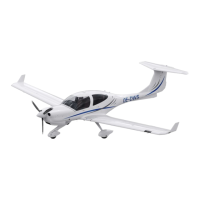
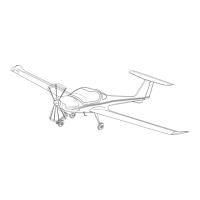
Displays the overall length, wingspan, height, and width of the DA40 NG aircraft.
Illustrates the placement of various antennas on the aircraft exterior.
Details temperature limits for airplane and outside air, including pre-heating requirements.
Specifies the maximum operating altitude for the aircraft.
Lists operational restrictions, including aerobatics and crosswind limits.
Presents empty weight, max takeoff, ramp, landing, and zero fuel weights.
Explains procedures for landing with masses between 1216 kg and 1280 kg.
Details standard and optional baggage capacities.
Lists key airspeeds like VNO, VNE, and V0 at various weights.
Shows stalling speeds (VS0, VS1) at different weights and bank angles.
Explains how ailerons, elevator, and rudder are actuated.
Describes the electrical and mechanical actuation of the flaps.
Introduces the Garmin 1000 integrated flight deck.
Identifies key instruments like Airspeed, Horizon, Altimeter, and Compass.
Highlights controls like Flood Lights, Emergency Switch, and Emergency Battery.
Points out Essential Bus and Electric Master Starter controls.
Illustrates the alternate static valve and its operational status.
Introduces the Garmin 1000 Engine Instrument System and refers to other modules.
Shows the layout of the Primary Flight Display (PFD) and Multi-Function Display (MFD).
Details the Engine Indication System (EIS) within the MFD.
Depicts the hydraulic brake system and pilot application.
Explains the parking brake mechanism and pressure trapping.
Provides a general description of the Austro Engine E4-A power plant.
Labels major components of the engine from various views.
Demonstrates the alternate air lever and valve positions.
Provides a block diagram of the Engine Control Unit and its connections.
Identifies the ECU test button and outlines its usage and test procedures.
Explains the causes and clearing procedures for ECU FAIL cautions.
Describes the propeller and how the governor operates with gearbox oil.
Lists procedures for oscillating RPM and RPM underspeed/overspeed.
Describes the engine-driven and electrical fuel pumps.
Lists limitations for overspeed, oil pressure, quantity, consumption, and temperature.
Outlines limitations for engine restart altitude and airspeed.
Specifies operating time and cool-down periods for the starter.
Lists approved jet fuels, diesel fuel requirements, and additives.
Details recommended engine and gearbox oils.
Lists checks before engine start and before takeoff.
Lists critical items for the parking check.
Describes warnings related to oil pressure and temperature.
Discusses oil pressure issues and refers to checklists for warnings.
Presents a schematic diagram of the aircraft's cooling system.
Illustrates coolant flow based on temperature and provides caution guidance.
Explains the cabin heating system and its control.
Shows cockpit and cabin ventilation controls and airflow.
Illustrates turbocharger components, airflow, and operational principles.
Details the capacity of standard and long-range fuel tanks.
Shows fuel valve location and normal/emergency system operation.
Identifies fuel cooler, transfer pump, and electrical pump operations.
Describes the fuel pressure warning annunciation and recommended actions.
Introduces diesel operation and G1000 software modifications.
Details operational limitations based on diesel fuel temperature.
Explains diesel fuel classes based on climatic zones.
Advises on switching fuels and fuel filter heating.
Highlights the amperemeter display on the G1000.
Identifies power sources and illustrates power distribution buses.
Illustrates battery power supply modes and bus configurations.
Shows essential power, total electric fail, and bus functions.
Introduces the GFC 700 Autopilot Flight Control System (AFCS).
Lists functions like Flight Director and Autopilot, and control panel layout.
Explains vertical speed, IAS hold modes, overspeed protection, and limitations.
Details how G1000 system losses affect autopilot functions.
Provides general performance data for takeoff and landing.
States the maximum demonstrated crosswind component.
Lists the various performance tables available in the manual.
Shows stalling speeds (VS0, VS1) at various weights and bank angles.
Provides methods for calculating takeoff distance including wind and slope effects.
Shows climb performance data for takeoff and cruise climb.
Offers methods for calculating landing distance considering wind and slope.
Explains how to calculate obstacle clearance and gradient.
Lists items included in the empty mass calculation.
Displays the center of gravity envelope chart.
Lists the lever arms for different aircraft components.
Details baggage capacity and limits for extended and short compartments.
Shows an example calculation for mass and balance.
Displays images of emergency equipment like a first aid kit.
Illustrates the steps for operating the emergency exit.
Lists required equipment for VFR and IFR operations, including instruments and lighting.
Notes additional equipment requirements based on operation and route.
Lists intervals for scheduled maintenance (hours and annually).
Identifies events requiring unscheduled maintenance.
Lists approved de-icing fluids and the procedure.
Provides guidance on parking, including short-term, extended, and cold weather.
Introduces the RACC system, its installation location, and components.
Explains the RACC concept and provides airflow schematics.
Lists limitations for RACC operation, including power switch and temperature conditions.
Details RACC operation on ground, with engine running, and in flight.
Shows the impact of RACC ON on takeoff ground roll and distance.
Illustrates the takeoff profile with key speeds and altitudes.
Depicts the landing profile with key speeds and procedures.
Provides information about the use and nature of checklists.
| Manufacturer | Diamond Aircraft Industries |
|---|---|
| Model | DA40 NG |
| Engine | Austro Engine AE300 |
| Power Output | 168 hp |
| Fuel Type | Jet A-1 |
| Seating Capacity | 4 |
| Type | Light aircraft |
| Maximum Speed | 178 knots |
| Cruise Speed | 150 knots |
| Service Ceiling | 16, 400 feet (5, 000 m) |
| Length | 26 ft 5 in (8.08 m) |
| Empty Weight | 1, 764 lbs (800 kg) |
| Takeoff Distance | 1, 050 feet (320 m) |
| Wingspan | 39 ft 4 in (12.0 m) |
| Height | 6 feet 6 inches (1.98 m) |