FUSE
FUSE
5
12
SYSTEM CONFIGURATIONS
Power/OverLoad Protection System LED’s - These lights indicate when the amplifier is powered up normally
and when there is a protection fault. The “OPS” LED is laminated when there is a problem with your amplifier. Please contact your authorized
Diamond Audio dealer or call our technical support.
1
Frequency Adjustment - Use this adjustment to select the crossover point. Remember that you must select the High
Pass position (HPF) Low Pass (LPF) or Full Range (FULL) from the Crossover Selection Switch first. The range of adjustment is limited
between 50-250 Hz, for BOTH HPF and LPF. Full Range is no filter, all pass frequncy.
5
Bass EQ - This control adds 0 to +12dB of boost at 45Hz. Be cautious when adding boost to some subwoofer systems as they may
not be able to handle the additional low frequency boost. In the 0dB position, no bass boost is added.
6
Crossover Selection Switch - This switch allows you to select the crossover. Use High Pass for midrange or high frequency
speakers. Use Low Pass for subwoofers. In the FLAT position, neither crossover adjustment knob has an affect and all speakers will receive the
full frequency range.
4
Level Adjustment(Input Gain) - This control matches the preamp stage of the Diamond Audio amplifier to your source unit.
This is NOT a volume control. The range is between approximently 200mV (0.2V) to 5V.
2
Line Input(RCA) - The RCA jacks allow for a normal Left and Right channel signal input. Simply connect to the source unit using
RCA type audio cables, keeping them away from power wiring wherever possible to reduce risk of noise.
Speaker Output Terminals - Connect your speakers to these terminals. Stereo connections are connected as labeled. Bridged
connections use the LEFT + and RIGHT - as the two connections. The 2 and 4 channel amplifiers will perform into 2 Ohm stereo loads or 4 Ohm
bridged loads. DO NOT run 2 Ohm bridged loads on these amplifiers! The mono blocks will run 2 ohms mono, BUT NOT 1 ohm mono!
9
7
Remote Level Control - MICRO1 amplifer has this port is for the remote level control (included). The control is intended to allow
the user to control the level of gain up to the maximum adjustment level set on the amplifier. The control does not add additional boost, it only
attenuates the setting that is fixed at the amplifier’s control panel.
10
8
Line Out (RCA)- This output allows for easy connection of signal into multiple amplifiers without the use of “Y-adaptors”
Power Input Connections -
These connections are for input power, chassis ground, and remote turn-on. Use a minimum of
8 gauge wiring for power and ground connections. 4 Guage is recommended for the mono block. The terminals will handle up to 8 gauge wiring
with no problem whatsoever(4 guage on the mono block). Be sure any wiring that passes through metal has a grommet!
11
Sub-Sonic Adjustment - This control allows you to remove the unwanted sub-sonic frequencies below the tuning frequency of
a ported enclosure. This helps to protect the woofer from over excursion.
12
Varible Phase - This control gices the installer a unique feature that allows the varible adjusment of phase 0-180 degrees to
compensate for subwoofer placement. Allowing the subwoofer to sound like it’s placed in the front of the vehicle instead of the trunk.
13
Clipping Indicator LED’s - These lights indicate when the amplifier is “clipping” (going into distortion) This could be casued
by over driving the input section and/or setting the input “gain” control to high. Remember that GAIN is NOT power output.
3
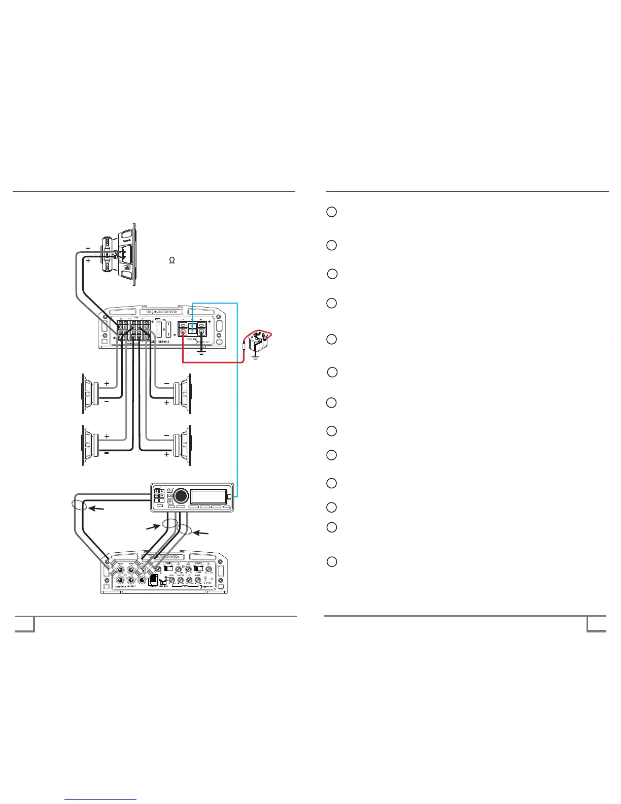
DE900.5D POWER/SPEAKER ENDPLATE
Battery
DE900.5D POWER/SPEAKER ENDPLATE
ESC
VIEW
BAND
SOURCE
AUDIO
MUTE FUNC
TAG
HEAD UNIT
(perferredly with 5V output)
PreAmp out
FRONT
PreAmp out
SUB
PreAmp out
REAR
FRONT
SPEAKERS
REAR
SPEAKERS
Subwoofer
(MIN 2 )
DE900.5D - Typical 5 Channel System
Setup - Front/Rear/Sub