-16-
The meter must not be under any mechanical stress when installed
in the pipeline.
Remove old seals and clean sealing faces.
Thinly grease sealing faces (use acid-free, potable-water approved
grease).
Only t the newly supplied seals (the seals should not intrude into
the pipeline).
Site-provided seals must be suitable for the purpose and comply with
the local guidelines and directives. No liability is accepted for conse-
quential damage resulting from the use of third-party seals such as
corrosion to sealing surfaces and threads.
Simultaneously manually screw home the meter ttings on both sides
and then tighten in opposing directions using a suitable tool (mini-
mum torque 30 Nm, maximum torque 50 Nm).
Depending on the version, the meter is suitable for water tempera-
tures from 0.1 °C to 90 °C.
Slowly ll the pipeline with water on completion of the installation.
The meter must always be lled full with water.
The meter must be protected against pressure shocks in the pipeline.
The meter may only be installed in frost-free areas.
Non-return valve
The meter can be supplied with a non-return valve (accessory) on
request (nominal diameter DN 15 - DN 40).
The non-return valve must be mounted in the meter outlet as shown
in g I for meters with a nominal diameter of DN 15 or g II for
meters with a nominal diameter for DN 20 and DN 40 or larger.
For meters with a nominal diameter of DN 25/32, a compensating ring
must be used to centre the non-return valve. (g. III).
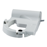
Coupling tting with collar
In order to prevent damage to the non-return valve, there is a PE
seal for the non-return valve (Fig. II and III) and coupling tting with
collar combination.
During the installation, the water meter must be held in this
position (see g. III) with a suitable tool to prevent damage to
the plastic housing.
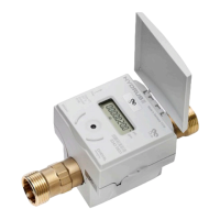
HYDRUS
Deutsch
English
Français Português