Module Modbus RTU
4 04/2019
4 MODULE INTERFACE
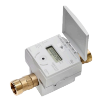
Fig.1
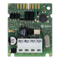
Meter
Internal connection using a
Diehl Metering cable ribbon
(P/N: 3013651)
Power
supply
Screw connector terminals :
60 (polarity independent)
61 (polarity independent)
EIA-485
Screw connector terminals :
90 (non-inverting, +)
91 (inverting, -)
Status
button
Used to restore device default
settings and check device
status.
Status LED
Used to signal transmission in
Modbus RTU network and to
confirm default setting
restore. Status LED lights up
when Status Button is
pressed.
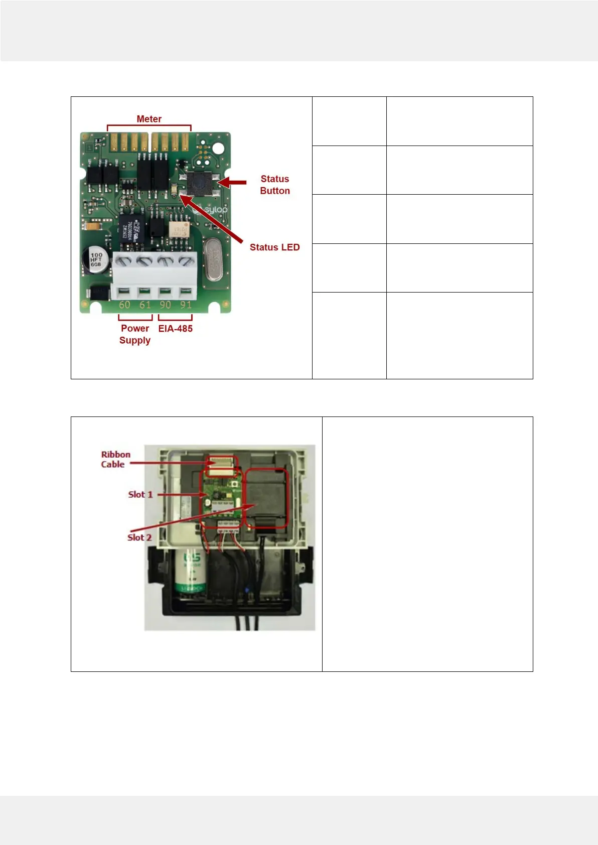
5 MODULE INSTALLATION
Fig.2
1. Open the meter by releasing side catches
and take front panel off as described in
Installation and User Guide for SHARKY 775
Ultrasonic Compact Energy Meter or
Installation and User Guide for SCYLAR INT 8
Calculator.
2 . Localize appropriate extension slot on front
panel back side.
3.
Place the module into one of slots (see
Picture 5.1). Ensure that the positioning
elements match the cuts on the module.
4. Press the module towards to front panel of
the meter to latch the module with the fixing
lug.
5. Check that module is stable installed in slot
6. Connect module with meter by ribbon
cable