Digi TransPort
®
WR11 Installation Guide
Page 6
Digi TransPort WR11 HSPA+ Model Specications
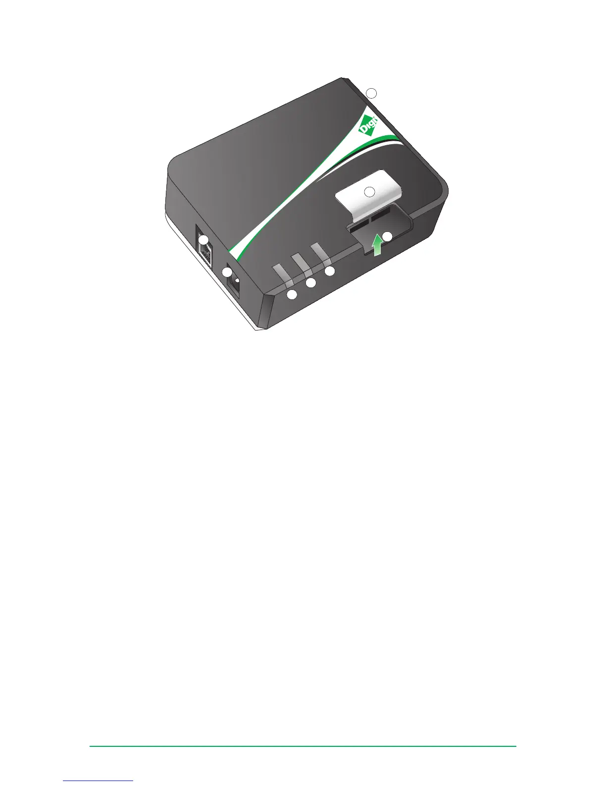
DIGI TRANSPORT WR11
Service
Signal
Power
1
2
3
4
5
6
7
8
SIM2
SIM1
1. LAN: This Ethernet port connects the device to a 10/100 base-T Local Area Network (LAN). The port is
capable of auto-sensing for speed and wiring, so it can accept both straight-through or cross-over cable
connections.
2. Power Cord Input: This locking power connector connects the device to a power source. The connector
should be inserted and rotated to lock in place.
3. LED Status Indicator - SERVICE: Blinks to show the device’s current network mode..
• Off: No cellular service
• 1 Blink: GPRS mode
• 2 Blinks: EDGE mode
• 3 Blinks: UMTS mode
• 4 Blinks: HSDPA mode
• 5 Blinks: HSUPA mode
4. LED Status Indicator - SIGNAL: This LED illuminates steadily when there is a network connection to the
WWAN interface and ashes when data is transmitted or received.
• Green: Signal strength >= -86dBm
• Amber: Signal strength between -87dBm and -101dBm
5. LED Status Indicator - POWER: This LED illuminates steadily when power is connected.
• Green: Device on
• Off: No power
6. SIM Door: Encloses the SIM sockets. The SIM door must be removed to install the SIM cards For
installation details, refer to the Quick Start Guide that came with your device.
Note: To remove the SIM door, hold the device on a at surface and using a screwdriver, rmly pull the cover
straight up.
7. SIM Sockets: SIM 1 and SIM 2 are for use with the Subscriber Identication Module(s) (SIMs).
8. Cellular Antenna Connector: This SMA female connector connects the device’s primary cellular antenna.
 Loading...