DR4018 DIGISWITCH (v1.34)
www.digikeijs.com Pagina / page / Seite / page 13
Modify the decoder’s sengs
There are two ways of changing the decoder’s sengs and/or switching me, or chosing one of the many presets
in CV47. They are described below.
(1) CV Programming / reading through the programming track
This common way of programming can become rather complicated.
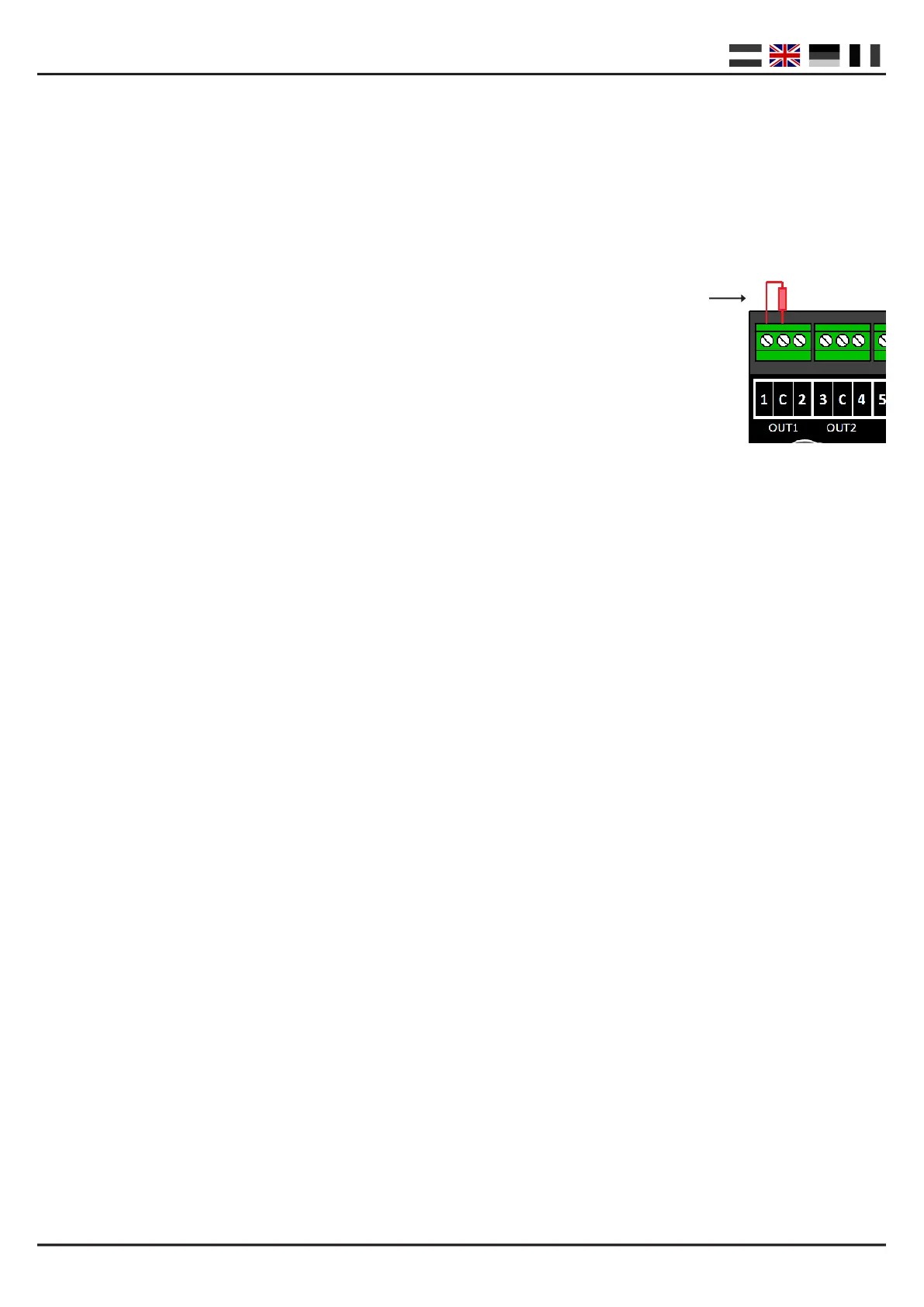
The decoder must rst be prepared by placing a 150—270 Ohm resistor on output 1 as shown in the diagram.
The resistor ensures that there is a resistance on the programming track, which your
control unit requires as conrmaon that a module is present and that the
programming commands have been received from the control unit.
Unfortunately, no two control units are the same and it is possible that the aached resistor
does not provide enough, or provides too much, resistance. If this happens,
consult your control unit’s manual to nd out what resistance is required. In most cases
using a bulb (12 Volt—60 mA) works well.
Step 1 : Connect both the power and signal inputs on the decoder to the rails output on your control unit.
Step 2 : Press the program buon on the module unl the red LED stays on.
Step 3 : Now connect both the power and signal input on the decoder to the program output on your control
unit.
Step 4 : You can now modify the CVs using CV byte or CV bit programming.
(For informaon about CV byte or CV bit programming, please consult your control unit’s manual)
Step 5 : Connect both the power and signal inputs on the decoder to the rails output on your control unit.
Step 6 : Press the program buon on the module unl the LED goes out.
Step 7 : Your modicaons have been saved and the module is ready for use.
(2) CV Programming via the main track (POM)
An alternave way of programming is POM (Program On Main). This method of programming allows you to con-
nect the module directly to the track without the diculty of aaching a resistor, as is required when program-
ming via a separate programming track.
Step 1 : Aach the signal input on the decoder to the rails output on your control unit.
Step 2 : Ensure the module is receiving power via the module’s power input.
(You can also connect the power and signal inputs to each other)
Step 3 : Set your control unit to POM programming mode.
(You can nd more informaon about the POM mode in your control unit’s manual)
Step 5 : Choose local address 9999 on your control unit.
Step 6 : Press the buon on the module unl the LED goes on.
Step 7 : Now program the desired CVs for the module.
Step 8 : Press the buon on the module unl the LED goes out.
Step 9 : The module is ready for immediate use with the modied sengs.
BE CAREFUL! In some cases the DR4018 must be given a new address by following the steps in the ‘Give the mo-
dule an address’ secon on page 3 of this manual.
 Loading...