DR4018 DIGISWITCH (v1.34)
www.digikeijs.com Pagina / page / Seite / page 14
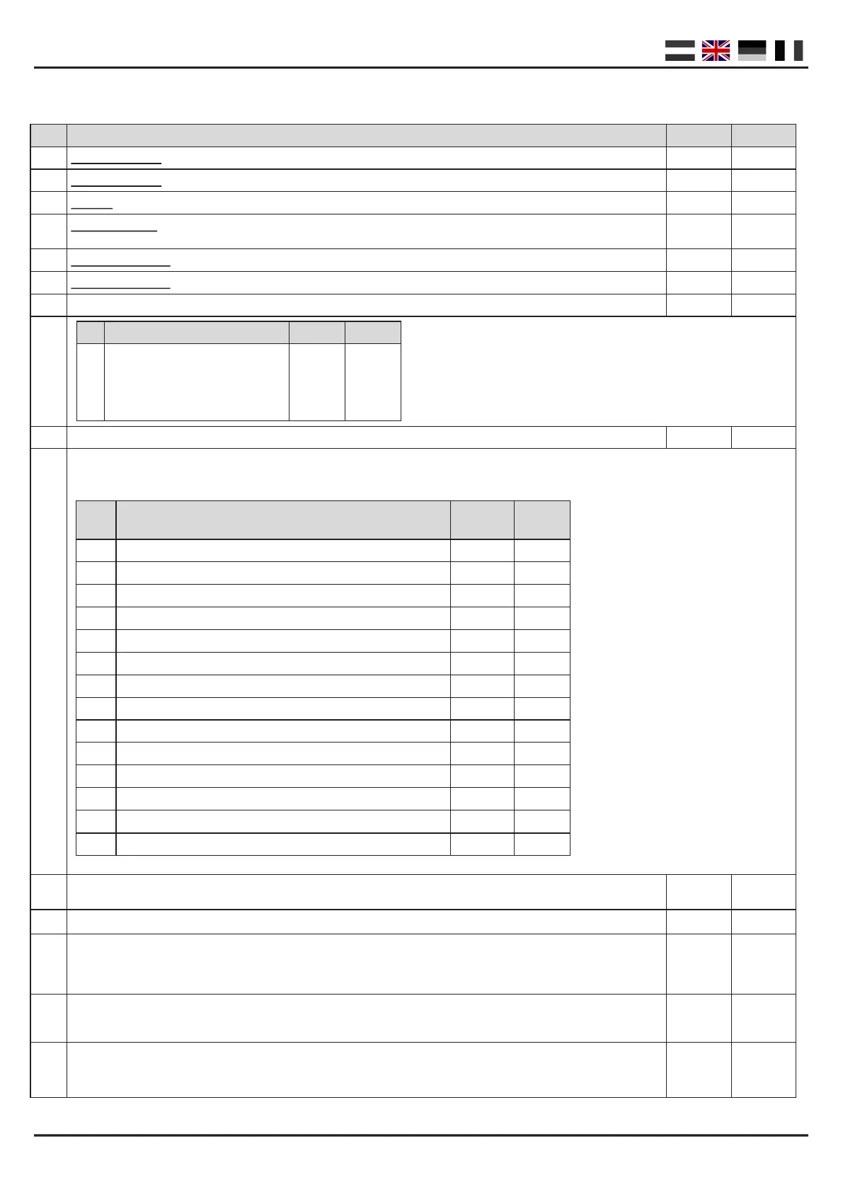
#
CV Definition Range Value
513
Primary Address Low
1-127 4
521
Primary Address High
1-127 0
7
Version of the decoder
- 134
8
Manufacturer ID Writing the value “8” will reset the decoder to it’s factory settings
- 42
17
Extended Address high byte
192-255 231
18
Extended Address low byte
128-255 15
29
Configuration Data
98
47
Presets (CV113 through CV128) WRITE ONLY
0 – 13 n/a
107 Dark time between signal transitions 1-255 70
108 Value to dim intensity of signal (night mode) 0-15 10
109
PWM Period The resolution with which the internal PWM operates to achieve effects and dim -values
1-255 14
111
Fade Speed The speed with which the outputs configured for fading will fade in and fade out
1-255 3
112
Blink rate The speed with which the outputs configured for blinking will blink
1-255 183
Bit Funcon Default Value
5
“0” = one byte addressing ( address in
CV1), “1” = two byte addressing (also
known as extended addressing, ad-
dress in CV17 and 18)
“0” 32
Preset Funcon Value
No. of
addresses
0 8x Turnout with twin-coil motor 0 8
1 16x permanent on/o switch 1 16
2 8x two-light signal with fade eect 2 8
3 8x AHOB 3 8
4 2 groups with 8x Fluorescent lamp 4 2
5 1 x 16 output with Fluorescent lamp 5 1
6 8x Turnout motor control 6 8
7 4x Dutch three-light signal 7 16
8 4x DB Main signal 8 16
9 4x DB pre-signal associated with main signal 9 16
10 2x Combinaon of DB Main signal and pre-signal 10 8
11 4x DB Pre-signal 11 16
12 4x NMBS Main signal 12 16
13 8x Turnout control with me limit 13 8
IMPORTANT! : This CV is not readable as entered values will not be stored, rather the entire decoder will be configured
according to the preset selected..
CV List
 Loading...