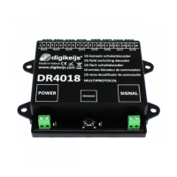
DR4018 DIGISWITCH (v1.34)
www.digikeijs.com Pagina / page / Seite / page 17
Signal funcon mapping output (EXPERT)
This table shows how the dierent signal numbers are coupled to output groups. It can be useful to change this
conguraon when you want to control both signals and points with the same module.
CV
OUTPUTS
1 –4 5—8 9-12 13-16
SIGNAL 1 143 1 2 4 8
SIGNAL 2 167 1 2 4 8
SIGNAL 3 191 1 2 4 8
SIGNAL 4 215 1 2 4 8
Output pulse mes
Use these CVs to congure the pulse duraon for outputs 1 through 16 provided they are set to pulse CV113=7
and CV47=13.
CV
CV Definition Range Value
238 Pulse time OUTPUT 1 0-255 128
239 Pulse time OUTPUT 2 0-255 128
240 Pulse time OUTPUT 3 0-255 128
241 Pulse time OUTPUT 4 0-255 128
242 Pulse time OUTPUT 5 0-255 128
243 Pulse time OUTPUT 6 0-255 128
244 Pulse time OUTPUT 7 0-255 128
245 Pulse time OUTPUT 8 0-255 128
246 Pulse time OUTPUT 9 0-255 128
247 Pulse time OUTPUT 10 0-255 128
248 Pulse time OUTPUT 11 0-255 128
249 Pulse time OUTPUT 12 0-255 128
250 Pulse time OUTPUT 13 0-255 128
251 Pulse time OUTPUT 14 0-255 128
252 Pulse time OUTPUT 15 0-255 128
253 Pulse time OUTPUT 16 0-255 128
Address Signal aspect
1
e
2
e
3
e
NS 3 lights with digit board
DB HP DB VR-Combi DB VR NMBS
R R R 0 Red HP0 Off VR0 Red
G R R 1 Green HP1 VR0 VR1 Flashing red
R G R 2 Yellow HP2 VR0 VR2 Double yellow
G G R 3 Flashing green with digit SH1 Off Off Flash double yellow
R R G 4 Yellow with digit HP1 VR1 VR0 Green yellow horiz.
G R G 5 Flashing green HP2 VR1 VR1 Green
R G G 6 Flashing yellow HP1 VR2 VR2 Flashing green
G G G 7 Yellow with flashing digit HP2 VR2 Off Green yellow vertical
Signal aspects
The combination of the first three addresses determines 1 of 8 possible signal aspects. The fourth address activates (night)
dimming.
R = Red button on your control unit
G = Green button on your control unit

 Loading...