Do you have a question about the Digikeijs DR4018 and is the answer not in the manual?
Details on the manufacturer's warranty, terms, and legal disclaimers for the product.
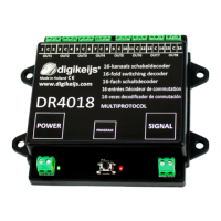
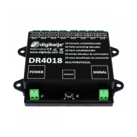
Provides detailed technical specifications, including output capabilities, protocol support, and power requirements.
Covers essential programming steps, including turnout address setting, CV manipulation, and resets.
Illustrates programming the DR4018 using various popular digital model railway control systems.
Key points to ensure successful programming, covering potential errors and general setup requirements.
Instructions on using turnout commands to set the decoder's address via the control panel.
Procedure for programming CVs directly on the main track using a compatible control panel.
Guidance on connecting and using the programming track for CV adjustments.
Step-by-step guide to perform a factory reset using the Program on Main (POM) method.
Procedure for performing a factory reset using the programming track connection.
Specific procedures for control panels that disable the programming track supply.
Guide for resetting the decoder when using control panels that affect programming track power.
Specific steps to set the initial turnout address on the DR4018 using Z21.
Guide for programming CVs on the main track using ROCO Z21/z21 with POM.
Steps to set the initial turnout address using the ROCO Multi-mouse.
Detailed instructions for programming CVs via POM using the ROCO Multi-mouse.
Steps for setting the initial turnout address with the Intellibox.
Guide for programming CVs via POM using the Uhlenbrock Intellibox.
Instructions for setting the initial turnout address with the LENZ LZV100.
Procedure for programming CVs via POM using the LENZ LZV100.
Solution for the red LED extinguishing during programming mode activation.
Diagrams showing connection options to the main track or external power supply.
Shows output connections for different presets configured via CV47.
Defines key CVs like Decoder Version, Manufacturer ID, and addressing modes.
Explains mapping outputs to function keys using vector group values.
Defines how signal numbers are connected to output groups for signal control.
Sets the pulse duration for outputs when configured for pulsating effects.
Describes signal patterns generated by integrated decoders based on CV settings.
| Brand | Digikeijs |
|---|---|
| Model | DR4018 |
| Category | Media Converter |
| Language | English |