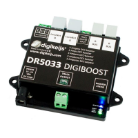
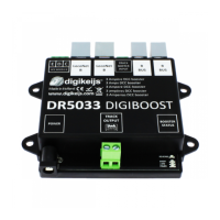
DR5033 BOOSTER 3 AMP
www.digikeijs.com P 6
Connecon
The DR5033 is connected to the control unit as indicated in the control unit manual.
• Lenz™ units: via the CDE output on the control unit to the CDE input on the DR5033
• Roco™ MulMaus™: via the booster-out on the control unit and the B-BUS™ input on the DR5033. Up to 4x DR5033 boosters
can be linked to each other (for more, a Roco™ 'braking module' is required; refer to the Roco™ manual).
• Roco z21™ (white): via the B-BUS™ output on the control unit and the B-BUS™ input on the DR5033. Up to 4x DR5033 boosters
can be linked to each other (for more, a Roco™ 'braking module' is required; refer to the Roco manual).
• Roco Z21™ (black): as for the z21 (white), with the addional opon of connecng the L.NET input on the DR5033 to the L-BUS
output on the Z21, enabling the features of an L.NET-connected DR5033 and enabling the DR5033 to be congured and read
out by the Z21™ maintenance tool using LNCV programming.
• Intellibox™ (I, I-IR, COM, Basic and II) / Fleischmann™ TwinCenter™ / Piko™ PowerPox™: via the LocoNet™ B output on the con-
trol unit to the L.NET input on the DR5033.
• Intellibox™ (I, I-IR): via the CDE connecon on the control unit to the CDE input on the DR5033.
• Other units that do not have CDE / B-BUS™ / L.NET can be connected via the rail output on the control unit to the RailSnier
input on the DR5033.
Conguraon
The DR5033 is set at the factory so that all of the control units tested (Lenz™ LZV100, Roco™ MulMaus™, Roco™ Z21™, Roco z21 ™
(white), Intellibox™, TwinCenter™ and DR5000) work out of the box.
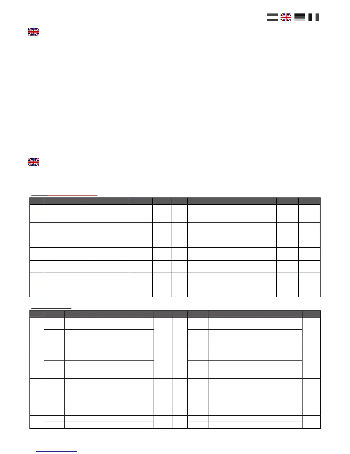
If you have a control unit that supports LNCV programming, you can congure the following on the DR5033:
LNCV Descripon Range Default LNCV Descripon Range Default
0 Module address 1-9999 1 12
The waing me aer automac polarity
reversal of the output prior to short circuit
being reported in 3 ms steps
32-250 48
1 Firmware version (1000 = 1.000) - - 13
The short-circuit or polarity-reversal raon
me in 3 ms steps
16-250 32
3 Conguraon Zie onder 92 14 Oponal switching address to reverse the 0-2048 0
6 H-bridge temperature in °C 0-150 - 15 Polarity reversal ON to feedback A 0-2048 0
7 Load percentage 0-100 - 16 Polarity reversal ON to feedback B 0-2048 0
8
Switching address to turn the booster on
or o
0-2048 0 17 Polarity reversal OFF to feedback D 0-2048 0
11
Turn on automacally following a short
circuit in 3 ms steps. The standard value
is equivaent to approx. 3/4 of a second
(750 ms)
64-30000 244 18 Polarity reversal OFF to feedback E 0-2048 0
Bit Value Descripon Default Bit Value Descripon Default
0
0 Not used
0 4
0
Booster sends no special L.NET report if there
is a short circuit.
16
1 Not used
16
Booster sends a special L.NET report if there
is a short circuit enabling the control unit to
display which booster has a short circuit.
1
0
Star the output from the booster as soon as
there is an input signal
0 5
0
Start the booster output without reversed
polarity (blue LED o)
0
2
Start the output from the booster when the
GO buon is pressed or the connected
switching address is 'green'
32
Start the booster output with reversed polari-
ty (blue LED on)
2
0
Booster sends no 'GPON/GPOFF' L.NET
report, even when there is a short circuit.
The automac short circuit repair is acve.
4 6
0 Automac polarity reversal o
64
4
Booster sends 'GPON/GPOFF' L.NET re-
ports. The control unit controls when the
booster turns back on.
64
Automac polarity reversal on
3
0 Not used
8 7
0 Not used
0
8 Not used 128 Not used
LNCV 3 Congurae
LNCV’s (order number 50330)
 Loading...