DVM-250/DVM-250Plus Installation Guide 860-00129-00 Rev C
Copyright © 2010-2015 Digital Ally, Inc. 3-3
11. Secure the cable and in-line fuse housing using Velcro or standard tie wraps as required. The
cable contains a filter to help minimize unwanted RF noise and 3 amp fuse.
12. Remove 4 to 5 inches of the outer jacket at the bare end of the power cable. Separate the
braided shield from the individual conductors, attach an electrical terminal to the end of the
braided shield, and attach the terminal to the chassis of the vehicle.
13. The Red wire of the DVM power cable should be connected to the vehicle +12Vdc and the Black
wire of this power cable connects directly to the vehicle’s chassis. It is preferred that the power
wire be tied in with DVM interface box connection with no obstructions to battery such as a
cutoff switch or charge guard system.
It is recommended that these connections are made directly to the engine compartment
battery wiring harness for best results. These wires should be used ONLY for the DVM system
and not be tapped into for installation of any other equipment in the vehicle. Doing so, could
result in possible radio frequency interference from the other equipment.
14. Connect the White wire to the ignition switch where +12vdc is only present when the vehicle
ignition Key is in the ON position.
Do not connect the White wire directly to the vehicle battery. For proper operation this wire
must be connected to the vehicle ignition switch.
15. Re-connect the cable to the connector on the back of the DVM.
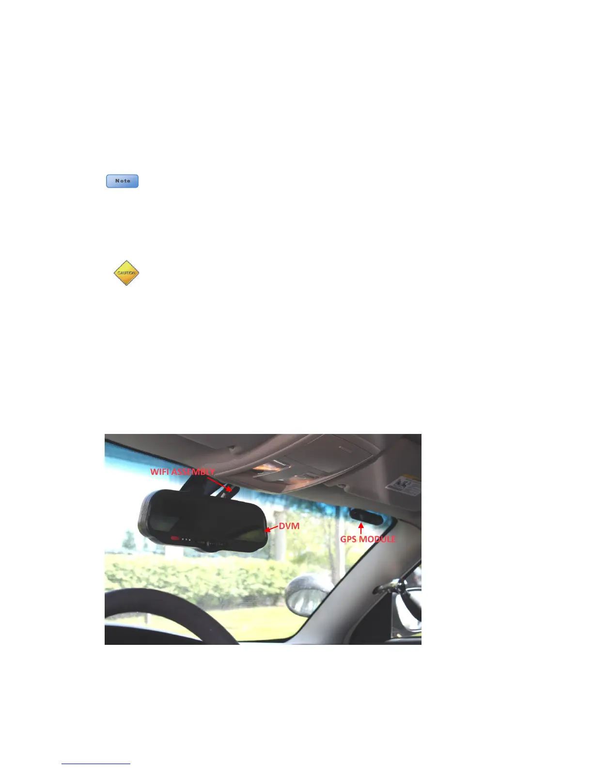
16. GPS Module and optional WIFI assembly
a. Use full length of cable to locate as GPS away from DVM
b. Upper right or left corner of windshield below the black "frit" of the top windshield.
c. Do Not mount the GPS:
i. In the headliner
ii. Under metal
iii. Near the DVM or Wi-Fi adapter
17. Clean the windshield glass with alcohol and use the supplied tape to attach the GPS module and
optional WIFI assembly to the windshield. See below.
18. If external triggers are not being used, proceed to “Section - 4: Testing the Installation"
 Loading...