DigitAx User Guide
Issue code: dgxu4
11-4
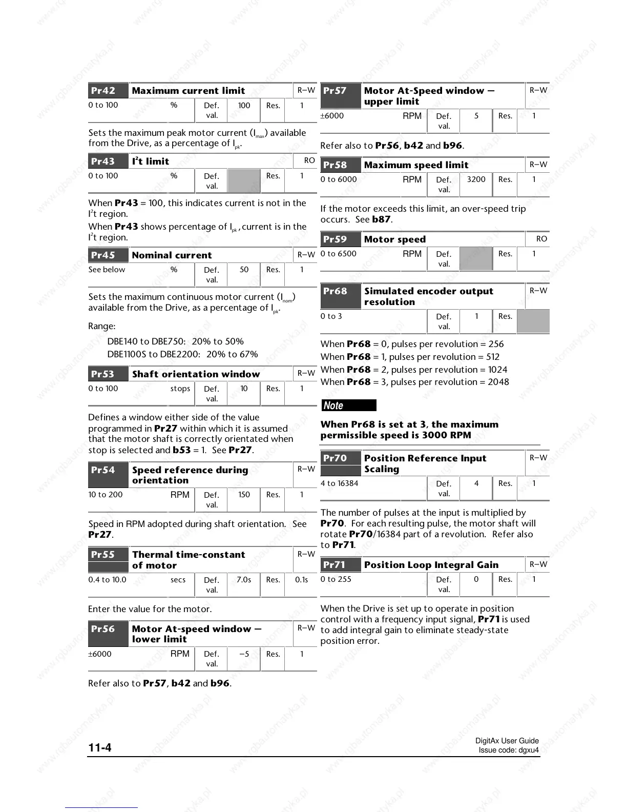
Pr42 Maximum current limit
R–W
0 to 100 %
Def
.
val.
100 Res. 1
Sets the maximum peak motor current (I
max
) available
from the Drive, as a percentage of I
pk
.
Pr43 I
2
t limit
RO
0 to 100 %
Def
.
val.
Res. 1
When Pr43 = 100, this indicates current is not in the
I
2
t region.
When Pr43 shows percentage of I
pk
,
current is in the
I
2
t region.
Pr45 Nominal current
R–W
See below %
Def
.
val.
50 Res. 1
Sets the maximum continuous motor current (I
nom
)
available from the Drive, as a percentage of I
pk
.
Range:
DBE140 to DBE750: 20% to 50%
DBE1100S to DBE2200: 20% to 67%
Pr53 Shaft orientation window
R–W
0 to 100 stops
Def
.
val.
10 Res. 1
Defines a window either side of the value
programmed in Pr27 within which it is assumed
that the motor shaft is correctly orientated when
stop is selected and b53 = 1. See Pr27.
Pr54 Speed reference during
orientation
R–W
10 to 200
RPM Def.
val.
150 Res. 1
Speed in RPM adopted during shaft orientation. See
Pr27.
Pr55 Thermal time-constant
of motor
R–W
0.4 to 10.0 secs
Def
.
val.
7.0s Res. 0.1s
Enter the value for the motor.
Pr56 Motor At-speed window —
lower limit
R–W
±6000
RPM Def.
val.
–5 Res. 1
Refer also to Pr57, b42 and b96.
Pr57 Motor At-Speed window —
upper limit
R–W
±6000
RPM Def.
val.
5 Res. 1
Refer also to Pr56, b42 and b96.
Pr58 Maximum speed limit
R–W
0 to 6000
RPM Def.
val.
3200 Res. 1
If the motor exceeds this limit, an over-speed trip
occurs. See b87.
Pr59 Motor speed
RO
0 to 6500
RPM Def.
val.
Res. 1
Pr68 Simulated encoder output
resolution
R–W
0 to 3
Def
.
val.
1 Res.
When Pr68 = 0, pulses per revolution = 256
When Pr68 = 1, pulses per revolution = 512
When Pr68 = 2, pulses per revolution = 1024
When Pr68 = 3, pulses per revolution = 2048
Note
When Pr68 is set at 3, the maximum
permissible speed is 3000 RPM
Pr70 Position Reference Input
Scaling
R–W
4 to 16384
Def
.
val.
4 Res. 1
The number of pulses at the input is multiplied by
Pr70. For each resulting pulse, the motor shaft will
rotate Pr70/16384 part of a revolution. Refer also
to Pr71.
Pr71 Position Loop Integral Gain
R–W
0 to 255
Def
.
val.
0 Res. 1
When the Drive is set up to operate in position
control with a frequency input signal, Pr71 is used
to add integral gain to eliminate steady-state
position error.
 Loading...