DigitAx User Guide
Issue code: dgxu4
11-6
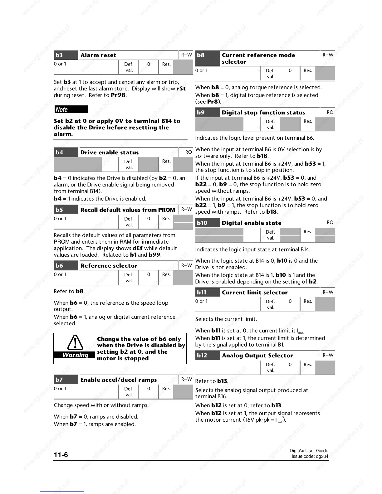
b3 Alarm reset
R–W
0 or 1
Def
.
val.
0 Res.
Set b3 at 1 to accept and cancel any alarm or trip,
and reset the last alarm store. Display will show rSt
during reset. Refer to Pr98.
Note
Set b2 at 0 or apply 0V to terminal B14 to
disable the Drive before resetting the
alarm.
b4 Drive enable status
RO
Def.
val.
Res.
b4 = 0 indicates the Drive is disabled (by b2 = 0, an
alarm, or the Drive enable signal being removed
from terminal B14).
b4 = 1 indicates the Drive is enabled.
b5 Recall default values from PROM
R–W
0 or 1
Def
.
val.
0 Res.
Recalls the default values of all parameters from
PROM and enters them in RAM for immediate
application. The display shows dEf while default
values are loaded. Related to b1 and b99.
b6 Reference selector
R–W
0 or 1
Def
.
val.
0 Res.
Refer to b8.
When b6 = 0, the reference is the speed loop
output.
When b6 = 1, analog or digital current reference
selected.
Warning
Change the value of b6 only
when the Drive is disabled by
setting b2 at 0, and the
motor is stopped
b7 Enable accel/decel ramps
R–W
0 or 1
Def
.
val.
0 Res.
Change speed with or without ramps.
When b7 = 0, ramps are disabled.
When b7 = 1, ramps are enabled.
b8 Current reference mode
selector
R–W
0 or 1
Def
.
val.
0 Res.
When b8 = 0, analog torque reference is selected.
When b8 = 1, digital torque reference is selected
(see Pr8).
b9 Digital stop function status
RO
Def.
val.
Res.
Indicates the logic level present on terminal B6.
When the input at terminal B6 is 0V selection is by
software only. Refer to b18.
When the input at terminal B6 is +24V, and b53 = 1,
the stop function is to stop in position.
If the input at terminal B6 is +24V, b53 = 0, and
b22 = 0, b9 = 0, the stop function is to hold zero
speed without ramps.
When the input at terminal B6 is +24V, b53 = 0, and
b22 = 1, b9 = 1, the stop function is to hold zero
speed with ramps. Refer to b18.
b10 Digital enable state
RO
Def.
val.
Res.
Indicates the logic input state at terminal B14.
When the logic state at B14 is 0, b10 is 0 and the
Drive is not enabled.
When the logic state at B14 is 1, b10 is 1 and the
Drive is enabled depending on the setting of b2.
b11 Current limit selector
R–W
0 or 1
Def
.
val.
0 Res.
Selects the current limit.
When b11 is set at 0, the current limit is I
max
When b11 is set at 1, the current limit is determined
by the signal applied to terminal B1.
b12 Analog Output Selector
R–W
Def.
val.
0 Res.
Refer to b13.
Selects the analog signal output produced at
terminal B16.
When b12 is set at 0, refer to b13.
When b12 is set at 1, the output signal represents
the motor current
(16V pk-pk ≡ I
peak
).
 Loading...