Do you have a question about the DigiTech TSR12 and is the answer not in the manual?
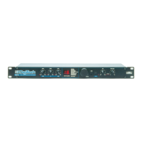
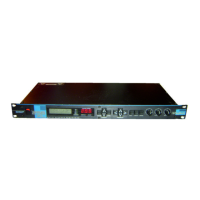
Overview of the DigiTech TSR-12 Studio Reverb / Multi-Effects System and its features.
Covers potential hazards and warnings for operating the TSR-12 safely.
Details the dangers of improper lithium battery replacement and handling.
Outlines the terms and conditions of the DigiTech product warranty.
Guidance on protecting the TSR-12 from power fluctuations and surges.
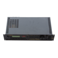
Detailed explanation of the TSR-12's front panel buttons, display, and indicators.
Explains the Parameter, FX Library, and Global buttons for program editing and navigation.
Details rear panel connectors and provides examples of MIDI and audio signal routing setups.
Describes the linear menu structure and the primary operating mode of the TSR-12.
Outlines the methods for recalling pre-loaded factory effect programs.
Step-by-step guide on tweaking existing factory presets to suit user needs.
Explains the role of function keys and FX library buttons in program creation and editing.
Covers the fundamental steps for creating new programs, including algorithm selection.
Details how to compare edited programs and assign custom names up to 16 characters.
Explains how to save programs and introduces the available effect modules like reverbs.
In-depth look at Bigverb and MFX Reverb parameters and their functions for creating reverb effects.
Describes gated reverb types and parameters, and introduces the Delay module family.
Details the parameters for various delay modules, including time, feedback, and repeat hold.
Explains the Chorus module types and their controls like level, speed, and depth.
Covers chorus waveforms and introduces Pitch Shifter modules and their parameters.
Details pitch shifting, detuning, and arpeggiator parameters for creative sound design.
Introduces the Sampler module and the various Equalizer modules available on the TSR-12.
Explains sampler functions and provides details on equalizer modules and their capabilities.
Explains the concept of Q factor in equalizers and its effect on bandwidth.
Details modulation effects including Tremolo, Auto Panner, and Flanger parameters.
Covers Phaser modules and the various Mixer module configurations for parallel effects.
Explains Noise Gate, Ducker, and Phase Inverter modules and their parameters.
Introduces the main Utility menu, accessing MIDI, Footswitch, and Contrast settings.
Details how to set the MIDI channel and configure Program Change message transmission.
Explains how to map MIDI program changes for external device control and receiving.
Guide on assigning MIDI Continuous Controllers to control TSR-12 parameters.
Explains how to view CC activity and how to perform a bulk memory dump.
Details dumping individual programs and assigning functions to the footswitch.
Covers assigning functions to footswitches and creating sequential program change lists.
Explains how to adjust screen contrast and select the output mode (mono/stereo).
Covers enabling/disabling the sales banner and restoring the unit to factory defaults.
Provides a comprehensive list of all factory presets and their associated algorithms.
Diagram showing the routing for the basic Dry Path algorithm.
Diagram illustrating the signal flow for the Delay and 8VoiceChorus algorithm.
Diagram showing the routing for the Chorus, Arpeggiator, and Delay algorithm.
Diagram illustrating the signal path for Chorus, Pitch Shift, and 4-Tap Delay.
Diagram for the Graphic EQ, Delay, and Chorus algorithm routing.
Diagram showing the signal flow for Graphic EQ, Delay, and Detune.
Diagram for Graphic EQ, Delay, and Flange algorithm routing.
Diagram showing the signal path for Graphic EQ, Delay, and Phaser.
Diagram illustrating the routing for the Graphic EQ and Big Reverb algorithm.
Diagram for Parametric EQ and Big Reverb algorithm signal flow.
Diagram showing the routing for Chorus and Reverb algorithm.
Diagram illustrating the signal path for Detune and Reverb algorithm.
Diagram for Flange and Reverb algorithm routing.
Diagram showing the signal path for Tremolo, Phaser, and Reverb.
Diagram for EQ, Delay, Reverb, and Gate algorithm routing.
Diagram illustrating the signal flow for EQ, Chorus, and 2TapPanners.
Diagram showing the routing for EQ, Chorus, 2Tap Delay, and Reverb.
Diagram for EQ, Detune, 2Tap Delay, and Reverb algorithm signal flow.
Diagram showing the signal path for EQ, Flange, 2Tap Delay, and Reverb.
Diagram for EQ, Phaser, 2Tap Delay, and Reverb algorithm routing.
Diagram illustrating the routing for Pitch Shift, 2Tap Delay, and Reverb.
Diagram showing the signal flow for EQ, Chorus, 4Tap Delay, and Pan.
Diagram for EQ, Detune, 4Tap Delay, and Pan algorithm routing.
Diagram illustrating the routing for EQ, Flange, 4Tap Delay, and Pan.
Diagram showing the signal path for EQ, Phaser, 4Tap Delay, and Pan.
Diagram for Pitch Shift and Reverb algorithm routing.
Diagram illustrating the signal flow for EQ and Gated Reverb.
Diagram showing the routing for Sampler and Graphic EQ.
Diagram for EQ, Delay, Reverb, and Ducker algorithm signal flow.
Diagram illustrating the routing for Chorus, Ducked 2Tap.
Diagram for EQ, Modulation Delay, and Reverb algorithm signal flow.
Diagram showing the signal path for EQ, Pitch Shift, 4Tap Delay, and Pan.
Details the analog-to-digital and digital-to-analog conversion specs and sampling rate.
Information on the Digital Signal Processor, data path width, and processing speeds.
Specifies connector types, nominal and maximum levels, and impedance for I/O.
Covers frequency response, S/N ratio, THD, memory, power, and dimensions.
| Brand | DigiTech |
|---|---|
| Model | TSR12 |
| Category | Recording Equipment |
| Language | English |