12
Adjustments
Casefeeder
It may be necessary to readjust the
micro-switch for different calibers.
Cases may become lodged between the
micro-switch and the tube wall. The
other extreme is the case failing to put
enough pressure on the micro-switch to
shut off the system causing it to con-
tinue running and over flowing the
tube.
Remove the two clutch screws
(#13732), lock washer (#13813) and
upper clutch (#13632) and the casefeed
plate. Place the spacer on the shoulder
of the lower clutch and reassemble –
see the schematic on page 31 for more
details. The casefeed plate should now
be approximately 1/8” above the floor
of the casefeed bowl. Note: Make sure
the casefeed plate is centered in the
bowl. Fig. 26
Handle
The operating handle is adjustable to
three different length settings Fig. 27.
Choose the one most comfortable for
your operation. Loosen the set screw
(#13432) then retighten when the handle
is in the most comfortable position.
Swager
Swaging on the Super 1050 is a simple
process and is necessary on all cartridge
cases as a means of uniforming the en-
trance of the primer pocket. Fig. 28 The
swage rod (#20314 large or #20313 -
small) is fully adjustable.
Swage Conversion and Adjust-
ment Conversion – Fig. 29
Begin by removing the swage cover
(#13064). Next remove the hitch pin
(#13840) and slide out the clevis pin
(#13522). Remove the operating handle.
Rotate the swage connecting rod a half
turn and remove it. This will allow you
access to the swager. Pull the swager
down and out of the machine. Fig. 29
Insert the new swager and reassem-
ble.
Swage Adjustments
Use ONLY an unswaged military case
for these adjustments.
With the handle in the down posi-
tion, screw the swage back-up ex-
pander down until it makes contact
with the case bottom and holds it in
place. Fig. 30
With the handle still in the down posi-
tion, turn the swage rod up until it makes
contact with the case bottom.
Raise the handle halfway and rotate
the swage rod a quarter turn. Now, cycle
the handle. Inspect the case and when
you achieve a completed swage of the
primer pocket, tighten the swage lock nut
(#14067).
A properly swaged pocket will show
a rounded edge around the rim. Some
military cases (.223 & .308) start out
with three small dents around the base
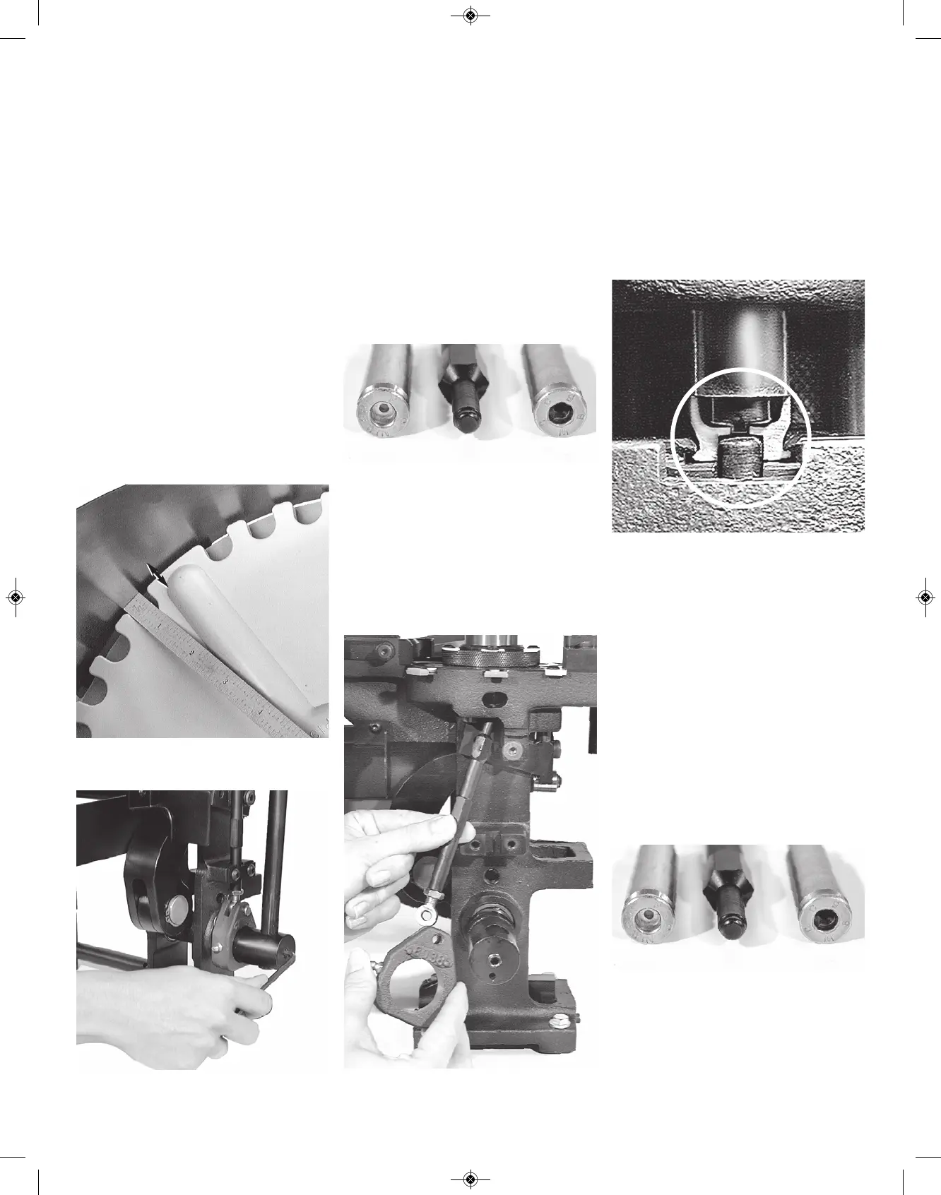
Fig. 26 - Make sure the casefeed plate is cen-
tered in the bowl with approximately 1/8”
all the way around.
Fig. 29 - See the schematics on page 28 for
more details.
Fig. 28 - Note the difference between the
swaged primer pocket (left) and the
unswaged primer pocket (right).
Fig. 31 - Note the difference between the
swaged primer pocket (left) and the
unswaged primer pocket (right).
Fig. 27 - Note that there are three different
positions for mounting the operating handle.
Fig. 30 - A cutaway view of a .45 ACP with
the swage rod and the back-up rod properly
adjusted in the swaging position.
1/8”