ASSEMBLY DimasTech Mini V.2.0 – STEP-3
- The DIMAS_23 component (3) has the
possibility of housing No.2 optical
readers inside it (items not included),
the image has the sole purpose of
illustrating the possible positions of the
parts.
- Align the side holes of the optical
reader with the slots of the DIMAS_23
component (3) and fasten with No°4
screws VC049_M3x6 (19) for each
optical reader, as shown in the figure
beside.
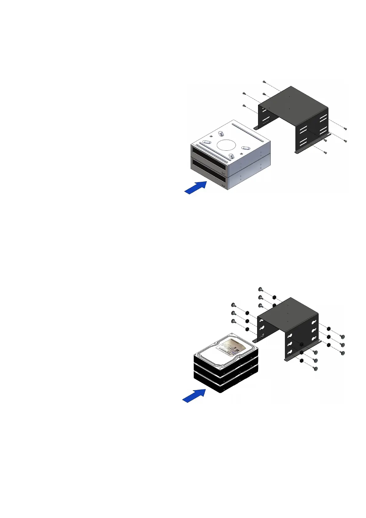
ASSEMBLY DimasTech Mini V.2.0 – STEP-4
- The DIMAS_24 component (4) has the
possibility to house inside No.3 hard-
disks (items not included), the image
has the sole purpose of illustrating the
possible positions of the parts.
- Insert No.12 VC019 (14) into the
appropriate shaped slots
- Align the side holes of the hard-disk to
the holes of VC019 (14) and fasten
with No.4 screws VC014_6-32 (15) for
each hard-disk, as shown in the figure
beside.
Note: The number indicated in the brackets indicates the corresponding
identification in the table on the page No.2
 Loading...