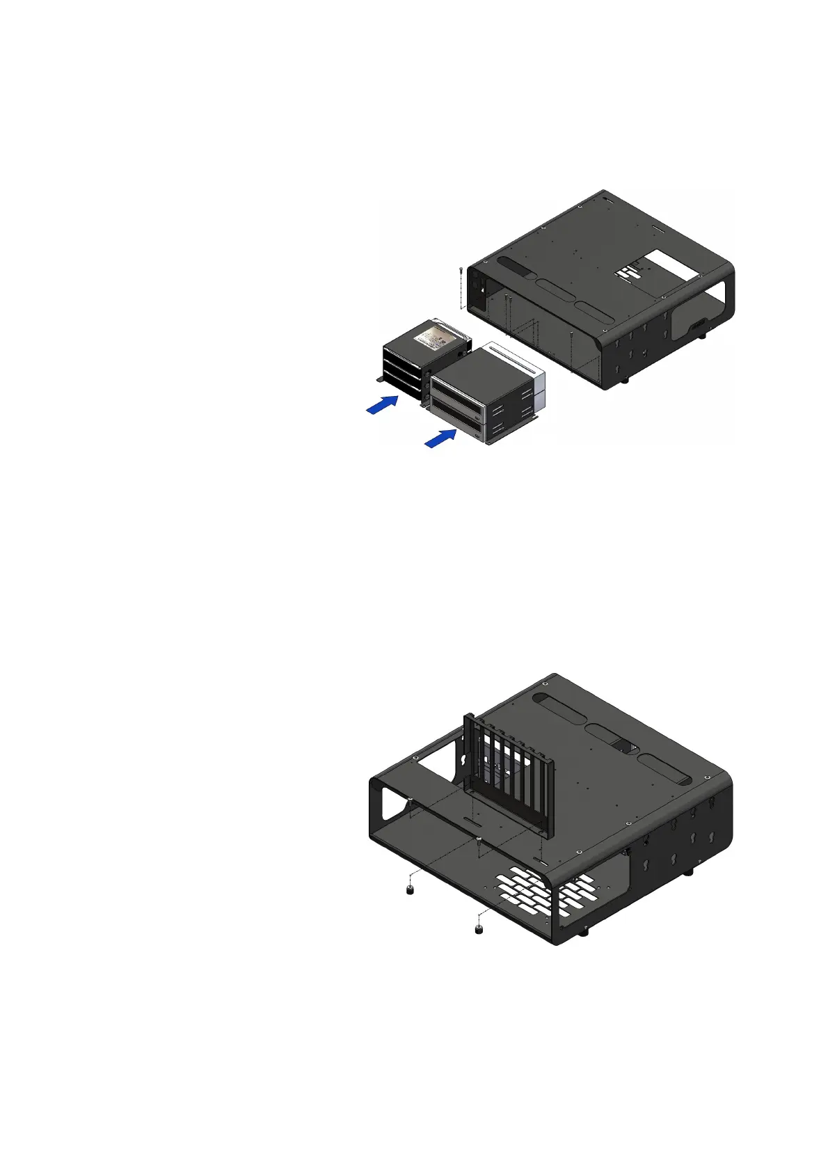
ASSEMBLY DimasTech Mini V.2.0 – STEP-5
- Insert the components
DIMAS_23 (3) and DIMAS_24 (4)
with the respective hardware
installed, inside the front of the
DimasTech Mini V.2.0 and fasten
with the No.4 screws
VC048_M3x10 previously
extracted, as shown in the figure
beside.
The image has the sole purpose
of illustrating the possible
positions of the parts.
ASSEMBLY DimasTech Mini V.2.0 – STEP-6
- Align the slots at the base of the
BT045-2013 component (5) with
the slots at the back of the
DimasTech Mini V.2.0 and fasten
with No.2 screws VC047_M4x10
(15) plus No.2 knurled nuts
VC024_M4 (17), as shown in the
figure beside
Note: The number indicated in the brackets indicates the corresponding
identification in the table on the page No.2
 Loading...