ASSEMBLY DimasTech Mini V.2.0 – STEP-7
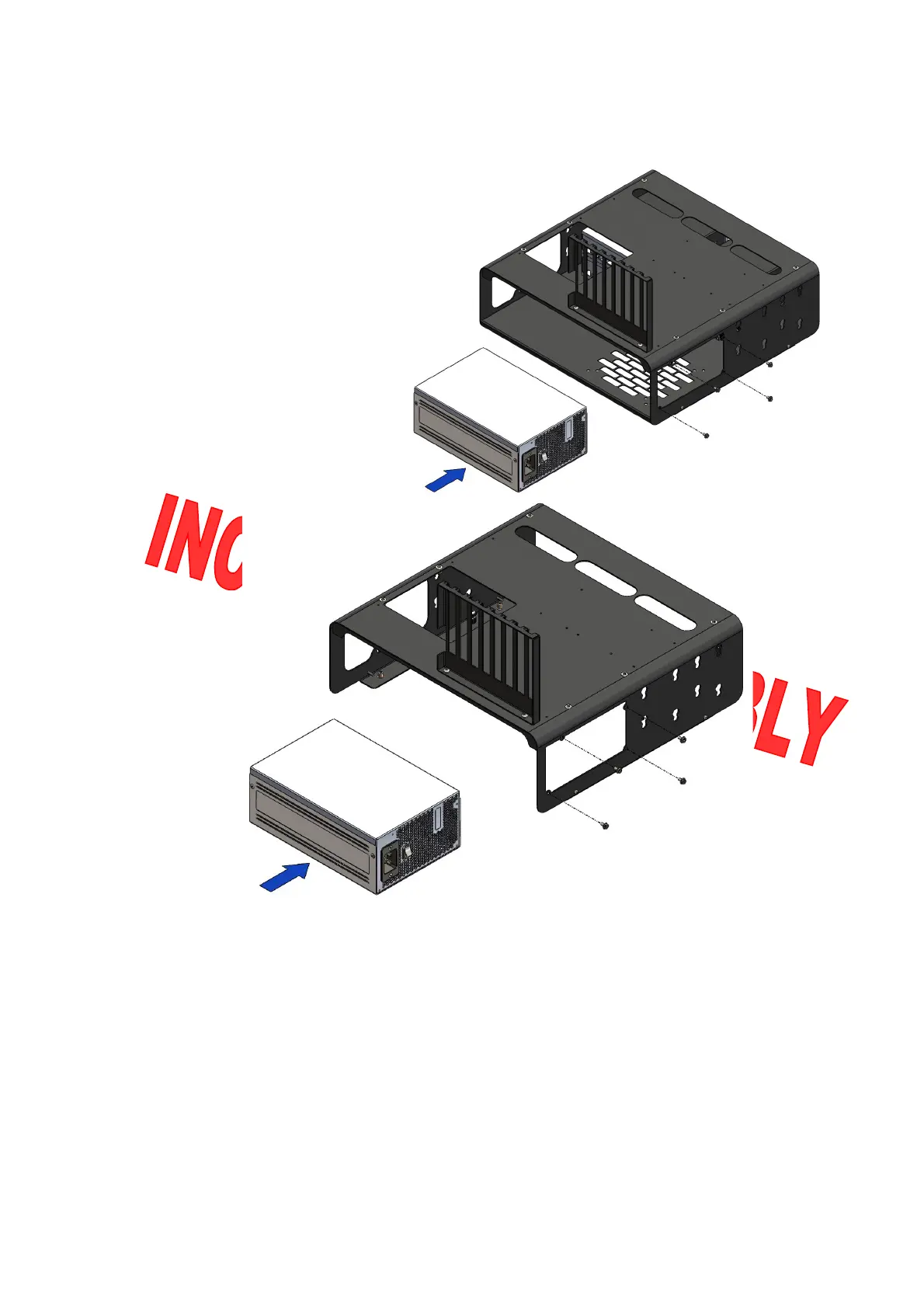
- The DimasTech Mini V.2.0 has
the possibility of housing No.1
power supply (PSU) inside (item
not included), the image has the
sole purpose of illustrating the
possible positions of the parts.
- Align the holes of the power
supply with the corresponding
DimasTech Mini V.2.0 holes and
fasten with No.4 screws VC066_6-
32 (18), as shown in the figure
beside.
OVERVIEWING IMAGE IS INDICATIVE OF AN INCORRECT MOUNTING
It is necessary, for a correct assembly, that the power supply (PSU) is inserted
inside the DimasTech Mini V.2.0 only if the body DIMAS_100_C_RF-RB_V.2.0 (1)
and the plan DIMAS_100_P_V.2.0 (2) are assembled, otherwise before
proceeding with STEP-7 it is necessary to install the DIMAS_100_P_V.2.0 plan
(2)
Note: The number indicated in the brackets indicates the corresponding
identification in the table on the page No.2
 Loading...