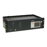
OPU-1
UNIVERSAL POWER-LINE CARRIER SYSTEM TYPE OPU-1
GENERAL DESCRIPTION - Rev 7 (May 2019)
5.2 HIGH-FREQUENCY CHARACTERISTICS
Programmable in 1 Hz steps
Selectable among 50, 75, 125 and 140
Better than 10 dB in accordance with IEC 495
In accordance with IEC 495, Fig. A.1 with n=4
(digital channel), figure 5 (analog channel)
Frequency separation for parallel
connection on the same line
(analog channel)
Between transmitter and receiver
of the same equipment
Between transmitters
of adjacent equipment
Between transmitter and receiver
of adjacent equipment
Between receivers
of adjacent equipment
Peak envelope power
over resistive load
20, 40 or 80 W, shared between the analog
and digital channels
Spurious emission
(analog channel)
In accordance with IEC 495 cls. 5.2.4 and
figures 7 and A.2
➢ Analog channel: -30 dBm (measured in the
pilot signal).
➢ Digital channel: -10 dBm
➢ Analog channel: higher than 65 dB at
300 Hz, and higher than 75 dB starting
from 4 kHz; in accordance with IEC 495
cls. 5.3.1.5.


 To Next Page